Frigidaire FFAD3533W1 Complete Owners Guide - Page 3
Wiring Diagram - dehumidifier
 |
View all Frigidaire FFAD3533W1 manuals
Add to My Manuals
Save this manual to your list of manuals |
Page 3 highlights
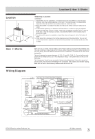
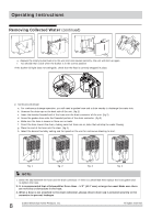
Location 12" 12" Location & How It Works Selecting a Location IMPORTANT: 1. Dehumidifier must be operated in an enclosed area to be most effective. Close all doors, windows, and other outside openings to the room. The effectiveness of the dehumidifier depends on the rate at which new moisture-laden air enters the room. 2. Place dehumidifier in a location that does not restrict the airflow of the air intake and air outlet. 3. A dehumidifier operating in a basement will have little or no effect in drying an adjacent enclosed storage area, such as a closet, unless there is adequate circulation of air in and out of the area. lt may be necessary to install a second dehumidifier in the enclosed area for satisfactory drying. 4. The dehumidifier must be installed on a level floor that will support it with a full bucket of water. 12" 5. There should be a minimum of 12 inches clearance around the dehumidifier. The unit will produce heat while in operation and should not be operated in an enclosed small space like a closet. How It Works When the unit is started, the fan begins to pull moisture-laden air across the dehumidifying coils. The coils condense or draw moisture from the air, and air flows through the air outlet louvers into the room as dry, warm air. Moisture removed from air is collected in a bucket on the front of the dehumidifier. The unit is designed to operate between 41 °F (5 °C), and 89 °F (32 °C). The unit will not work properly if the temperature is out of this temperature range, or the performance of the unit will fall greatly. The "Compressor" circuit has an automatic 3 minute time delayed start if the unit is turned off and on quickly. This prevents overheating of the compressor and possible circuit breaker tripping. Make sure the tank is fitted correctly otherwise unit will not turn on. Wiring Diagram 16020100001654 Notes: Display and Fan's conntors must be match the actual indicates. FAN BLUE TOP M STEP Notes: This symbol indicates the element is optional, CAPACITOR BROWN Y/G PUMP RED BLACK(or BLUE) OPTIONAL CN2 CN1 DC POWER BOARD FAN TOUCH/LIGHT PANEL WIFI WATER PIPE HUMI. SWITCHTEMP. SENSOR CN5 DISPLAY BOARD CN11 CN10 (or CN13) CN12 WIFI SWITCH SWITCH RED BLACK(or BLUE) WHITE the actual shape shall prevail BLUE RED Y/G ION BLACK COMP. BLUE BLACK ~ M M SC Y/G COMP. OverLoad CAPACITOR Protector WHITE(OR BLUE OR BLACK)(N) P4 P9 P6 P10 CN4 CN3 CN2 CN1 CN10 CN7 CN6B MAIN BOARD CN5 (or CN6/CN6A/CN6B/CN6C/CN10) P7 P2 P1 CN14 P8 13 CN15 12 Y/G(or GREEN) POWER RED BLACK(OR BROWN OR RED)(L) 3 POWER 1 1 BOARD 2 CN1 CN2 2019 Electrolux Home Products, Inc. All rights reserved. 3
-
 1
1 -
 2
2 -
 3
3 -
 4
4 -
 5
5 -
 6
6 -
 7
7 -
 8
8 -
 9
9 -
10
-
11
 |
 |
