Frigidaire FFIF3054TS Wiring Diagram - Page 1
Frigidaire FFIF3054TS Manual
 |
View all Frigidaire FFIF3054TS manuals
Add to My Manuals
Save this manual to your list of manuals |
Page 1 highlights
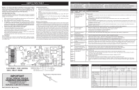
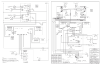
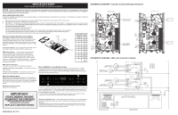
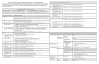
SERVICE DATA SHEET Electric Ranges with 3XX Electronic Oven Controls NOTICE - This service data sheet is intended for use by persons having electrical and mechanical training and a level of knowledge of these subjects generally considered acceptable in the appliance repair trade. The manufacturer cannot be responsible, nor assume any liability for injury or damage of any kind arising from the use of this data sheet. SAFE SERVICING PRACTICES To avoid the possibility of personal injury and/or property damage, it is important that safe servicing practices be observed. The following are examples, but without limitation, of such practices. 1. Before servicing or moving an appliance remove power cord from electrical outlet, trip circuit breaker to OFF, or remove fuse. 2. Never interfere with the proper installation of any safety device. 3. GROUNDING: The standard color coding for safety ground wires is GREEN or GREEN WITH YELLOW STRIPES. Ground leads are not to be used as current carrying conductors. It is extremely important that the service technician reestablish all safety grounds prior to completion of service. Failure to do so will create a potential safety hazard. 4. Prior to returning the product to service, ensure that: • All electric connections are correct and secure. • All electrical leads are properly dressed and secured away from sharp edges, high-temperature components, and moving parts. • All uninsulated electrical terminals, connectors, heaters, etc. are adequately spaced away from all metal parts and panels. • All safety grounds (both internal and external) are correctly and securely reassembled. Oven Calibration Set the electronic oven control for normal baking at 350°F. Obtain an average oven temperature after a minimum of 5 cycles. Press Stop, Clear, Off or Cancel to end Bake mode. Temperature Adjustment 1. Set EOC to bake at 550°F. 2. Within 5 seconds of setting 550°F, press and hold the bake pad for approximately 15 seconds until a single beep sounds (longer may cause F11 shorted keypad alarm). 3. Calibration offset should appear in the display. 4. Use the slew keys to adjust the oven temperature up or down 35°F in 5°F increments. 5. Once the desired (-35° to 35°) offset has been applied, Press Stop, Clear, Off or Cancel. Note: Changing calibration affects normal Bake mode. The adjustments made will not change the Self-Cleaning cycle temperature. Modular Control Systems This appliance is equipped with a modular system of controls. The modular system consists of various boards which communicate with one another to drive cooking functions. Oven functions, if available, operate through an oven user interface (UI or UIB) and an oven relay board. Cooktop functions, if available, operate through a cooktop UI/UIB and a cooktop relay board. There may be additional boards which work within the system to drive specific functions (refer to the schematics and diagrams and this sheet). Low voltage operating and communications power for the modular boards is provided through the wiring schemes. The boards that generate low voltage operating and communications power depend upon the individual control system (refer to the schematics and diagrams on this sheet). These voltages are only the operational voltages. Do not use these voltages as confirmation of communication between the boards. Communication occurs through software programming on each board. This communication is not detectable by volt ohmmeters. The programming is self-monitored and the UI displays will show error codes based on detected failures. The individual boards are not field repairable. See the schematics and diagrams included on this sheet for more unit-specific details. 15 ELECTRONIC OVEN CONTROL (EOC) RELAY BOARD TEMPERATURE PROBE TEMPERATURE PROBE DOOR SWITCH LOCK SWITCH IMPORTANT DO NOT REMOVE THIS BAG OR DESTROY THE CONTENTS WIRING DIAGRAMS AND SERVICE INFORMATION ENCLOSED REPLACE CONTENTS IN BAG 808532550 REV A EN (2017/06) OVEN LIGHT SPEED BAKE IND MDL SPEED BAKE FAN BAKE BROIL BAKE BROIL L1 L2 OUT L2 IN 1 DLB - DOUBLE LINE BREAK NEUTRAL LOCK MOTOR OVEN LAMP COMMON Resistance Temperature Detector Tech Sheet Abbreviations and Terminology EOC = Electronic Oven Control ESEC = Electronic Surface Element Control UIB = User Interface Board TSEC = Touch Sensor Electronic Control VSC = Variable Speed Control PS = Power Supply Board (PS1, PS2, etc. ) TST = Touch Sensor technology (touch control glass panel ) RTD = Resistance Temperature Device (Temp Probe or Temp Sensor) TCO = Thermal Cut Out also "Thermo Disc" or "Thermal Limiter" Electric Oven Control Fault Description Fault Code Likely Failure Condi- Suggested Corrective Action ton/Cause F10 Runaway temperature If Oven is cold: Oven heats when no 1. If fault code is present with cold oven test oven temperature sensor probe circuit resistance. Use RTD scale found in the cook cycle is pro- tech sheet. grammed. 2. Replace probe or repair wiring connections if defective. 3. If temperature sensor probe circuit is good but fault code remains when oven is cold, replace the EOC. If Oven is overheating: 1. If oven is severely overheating/heating when no cook cycle is programmed test oven temperature sensor probe circuit resistance using the RTD scale found in the service tech sheet. Also verify that the temperature sensor probe in proper- ly installed in the oven cavity. 2. Disconnect power from the range, wait 30 seconds and reapply power. If oven continues to heat when the power is reapplied, replace the EOC. NOTE: Severe overheating may require the entire oven to be replaced should damage be extensive. F11 Shorted keypad or selector switch 1. Reset poor supply to range - Disconnect power, wait 30 seconds and reapply power. 2. Check/ reset ribbon harness connections between touch panel and EOC. 3. Test keyboard circuits. Replace touch panel if defective. 4. If keyboard circuits check good, replace the EOC. F13 Shorted oven sensor 1. Disconnect power, wait 30 seconds and reapply power. If fault returns upon power-up, replace EOC. probe circuit. F14 Keyboard tail failure 1. Check for damage to the ribbon connection or that it is plugged in properly. F20 Communication failure 1. Reset power supply to range - Disconnect power, wait 30 seconds and reapply power. between oven and cook- 2. Check/reseat communication between oven (MACS BUS) and cooktop controller (MACS2) top control boards 3. If problem persists, replace each board individually then retest until problem clears F30 Open oven sensor probe 1. (F30) Check resistance at room temperature & compare to RTD Sensor resistance chart. If resistance does not match circuit. the RTD chart, replace RTD Sensor Probe. Check Sensor wiring harness between EOC & Sensor Probe connector. F31 Shorted oven sensor probe circuit. 2. (F31) Check resistance at room temperature, if less than 500 ohms, replace RTD Sensor Probe. Check for shorted Sensor Probe harness between EOC & Probe connector. If resistance is correct, replace the EOC. F40 Communication failure 1. Reset power supply to range - Disconnect power, wait 30 seconds and reapply power. between oven and cook- 2. Check/reseat communication between oven (MACS BUS) and cooktop controller (MACS2) top control boards 3. If problem persists, replace each board individually then retest until problem clears F90 Door lock motor or latch If lock motor runs: circuit failure. 1. Test continuity of wiring between EOC and lock switch on lock motor assy. Repair if needed. F91 2. Advance motor until cam depresses the plunger on lock motor switch. Test continuity of switch contacts. If switch is open replace lock motor assembly. F92 3. If motor runs and switch contacts and wiring harness test good, replace the EOC. If lock motor does not run: F93 1. Test continuity of lock motor windings. Replace lock motor assembly if windings are open. 2. Test lock motor operation by using a test cord to apply voltage. If motor does not operate, replace lock motor assy. F94 3. If motor runs with test cord check continuity of wire harness to lock motor terminals. If harness is good, replace the EOC. F95 RTD SCALE Temperature °F (°C) 32 ± 1.9 (0 ± 1.0) 75 ± 2.5 (24 ± 1.3) 250 ± 4.4 (121 ± 2.4) 350 ± 5.4 (177 ± 3.0) 450 ± 6.9 (232 ± 3.8) 550 ± 8.2 (288 ± 4.5) 650 ± 9.6 (343 ± 5.3) 900 ± 13.6 (482 ±7.5) Probe circuit to case ground Resistance (ohms) 1000 ± 4.0 1091 ± 5.3 1453 ± 8.9 1654 ± 10.8 1852 ± 13.5 2047 ± 15.8 2237 ± 18.5 2697 ± 24.4 Open circuit/infinite resistance Circuit Analysis Matrix Bake/ Time Bake Conv/Speed Bake Broil Clean Unlocked Locking Unlocking L1 to Bake X X X L1 to Broil X* X* X EOC RELAYS L1 to Motor Door Latch L1 to Conv/ Speed Bake Fan X X X Door Closed Cooktop Active Note: X=Check listed circuits. *=Alternates with Bake element L1 to Conv/ Speed Bake Ind Light X Door Switch COM-NO Cooktop Lockout X X
-
 1
1 -
 2
2 -
 3
3 -
 4
4
 |
 |
