Frigidaire FFIF3054TS Wiring Diagram - Page 4
Electronic Surface Element Control System ESEC Error Code Descriptions
 |
View all Frigidaire FFIF3054TS manuals
Add to My Manuals
Save this manual to your list of manuals |
Page 4 highlights
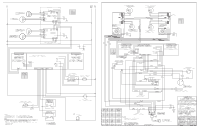
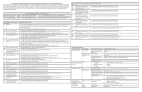
Electronic Surface Element Control System (ESEC) Error Code Descriptions When a specific error condition occurs in the ESEC system, a code will be displayed in the electronic control panel as shown in the error notification in an induction system section. For each Error Code there is a listing of the likely cause or failure condition, as well as suggested corrective actions to be taken. Always reset the power by disconnecting or turning off the power supply for 30 seconds to see if the failure condition will clear. If the error code returns perform the steps one at a time in the order listed below to correct the specific failure condition. NOTE: If multiple changing error codes are displayed check for disconnected wires or cables. EOC = Electronic Oven Control UIB = User Interface Board VSC = Variable Speed Control Tech Sheet Abbreviations and Terminology ESEC = Electronic Surface Element Control TST = Touch Sensor Technology (touch control glass panel) TSEC = Touch Sensor Electronic Control RTD = Resistance Temperature Device. (Temp Probe or Temp Sensor) PS = Power Supply board (PS1 , PS2, etc.) TCO = Thermal Cut Out also "Thermo Disc" or "Thermal Limiter" Error Code 011 Likely Cause or Failure Condition Stuck key 012 Keyboard configuration error Suggested Corrective Action 1. If a key was pressed inadvertently for a long time this error code will be displayed. Make sure there is nothing (water, utensils) in contact with the keyboard. The fault code should go away once the key is released and the Stop key is pressed. If the F011 error comes back when a key is pressed it means the error condition is still there. If the F011 error does not come back it means the error condition is gone and the oven can be used. 2. If the fault code cannot be cleared, replace the oven/cooktop control. 1. Verify the unit has the proper cooktop user interface board based on the model number and parts catalog. 2. Replace the oven/cooktop control if incorrect or the issue persists. 013 Non-volatile memory alarm 1. Disconnect power, wait 30 seconds and reapply power. If fault returns upon power-up, replace oven/cooktop control. 020 Loss of communication between cooktop UI and oven UI 1. Check all harness connections between user interface board and generator board, including all jumper connections (see schematic). 2. If problem persists, check continuity of harness between each control board and user interface. 3. If problem persists, check low voltage (refer to wiring diagram) between the oven control and user interface board. If loss of communication is detected, verify low voltage going in and out of boards and harnesses. 4. If problem persists, replace the oven/cooktop control. 022 Loss of communication between 1. Check all harness connections between user interface board and generator board, including all jumper connections (see schematic). generator board and user interface 2. If problem persists, check continuity of harness between each control board and user interface. Replace harness if defective. board. 3. If problem persists check low voltage (refer to wiring diagram) between the oven control and oven/cooktop control. Also, check for low voltage between the oven/cooktop control and Induction boards 1 and 2. If loss of communication is detected, verify low voltage going in and out of boards and harnesses. 4. If harness is good and problem persists, replace induction generator board 1. 5. If problem persists, reinstall original induction generator board 1 and replace induction generator board 2. 126 Macs communication mismatch 226 1. Disconnect power to the unit, wait 30 seconds, then reapply power. 2. If fault persists, replace oven/cooktop control. 035 ON indicator display failure: the 1. Disconnect power to the appliance, wait 30 seconds before reconnecting power. displays cannot display the LEDs 2. If problem persists, replace oven/cooktop control. properly, the mechanism for the displays has failed. 149 Induction generator board configu- 1. Cycle power to the appliance, wait 30 seconds before reconnecting power. 249 ration compatibility error. 2. Has the appliance been recently serviced? If so, verify the part numbers of the replaced components. Incorrect replacement parts will cause software errors. 3. If parts check correctly and the problem persists, replace the induction board indicated by the error code. 4. If problem persists, replace the oven/cooktop control. 051 Unable to read cancel key/tail sense error 1. Disconnect power to the unit, wait 30 seconds, then reapply power. 2. Test wiring harness between left and right cooktop UI's (J1 connector on each board). 4. If fault persists, replace the oven/cooktop control. 157 MAINS (power supply) relay stuck 1. Cycle power to the appliance, wait 30 seconds before reconnecting power. 257 on induction powerboard. 2. If problem persists, replace the induction board indicated by the error code. 158 400v detection error on induction 1. Cycle power to the appliance, wait 30 seconds before reconnecting power. 258 powerboard. 2. If problem persists, replace the induction board indicated by the error code. 159 Too low mains voltage detected on 1. Check line voltage coming into the appliance. 259 induction generator board 2. If problem persists, replace the induction board indicated by the error code. 161 15v supply out of window on 261 induction generator board 1. Cycle power to the appliance, wait 30 seconds before reconnecting power. 2. If problem persists, replace the induction board indicated by the error code. 164 Cooling fan on the induction 264 generator board is blocked or otherwise unable to turn. 1. Check for interference, blockages, debris, dust, or anything else that would physically prevent the fan from moving. 2. If problem persists, replace the induction board indicated by the error code. 165 Open temperature sensor on 265 induction coil. 1. Verify that induction coil temperature sensor is connected to generator (B71 & B81). 2. Test resistance of each sensor for ± 100K ohms at room temperature. Replace coil if sensor is open or shorted. 3. If problem persists replace the induction generator board indicated by the error code. 167 Loss of communication between 267 control and power micros on induction generator board 1. Cycle power to the appliance, wait 30 seconds before reconnecting power. 2. If problem persists, replace the induction board indicated by the error code. Error Code 168 169 268 269 170 270 171 271 172 272 173 273 174 274 Likely Cause or Failure Condition Suggested Corrective Action Failure check found inconsistent voltage or current measurement between the two induction generator board microprocessors. Failure check found inconsistent power frequency detection between the two induction generator board microprocessors. Failure check found inconsistent power currents between the drive circuit for the coils (IGBT) and the main power current on the induction generator board. Internal syncing error between the two induction generator board microprocessors Failure check found too-high temperature on induction generator board. Heat sink sensor open or shorted. 1. Cycle power to the appliance, wait 30 seconds before reconnecting power. 2. If problem persists, replace the induction board indicated by the error code 1. Cycle power to the appliance, wait 30 seconds before reconnecting power. 2. If problem persists, replace the induction board indicated by the error code. 1. Cycle power to the appliance, wait 30 seconds before reconnecting power. 2. If problem persists, replace the induction board indicated by the error code. 1. Cycle power to the appliance, wait 30 seconds before reconnecting power. 2. If problem persists, replace the induction board indicated by the error code. 1. Cycle power to the appliance, wait 30 seconds before reconnecting power. 2. If problem persists, replace the induction board indicated by the error code. 1. Check that the sensor is installed correctly, measure approximately 100K Ohm for NTC.. 2. If problem persists, replace the induction board indicated by the error code. 175 Failure check found a bad sensor 1. Check the sensor connections on the induction board indicated by the error code. 275 or a shorted circuit on the induction 2. If problem persists, replace the induction board indicated by the error code. generator board. 180 Power supply and/or frequency lost 1. Cycle power to the appliance, wait 30 seconds before reconnecting power. 280 on the induction generator board. 2. If problem persists, replace the induction board indicated by the error code. 181 Cooling fan not connected on induc- 1. Check cooling fan connections on the induction board indicated by the error code. 281 tion generator board. 2. If problem persists, replace the induction board indicated by the error code. Additional Failure Conditions Symptom or Failure Control Display Pan does not heat up. Normal operation Flashing power level Display and pan does not heat. Individual buttons cannot None be used or cannot always be used. Cooking power too low or shuts down prematurely. None Normal Operation Possible Cause or Condition Pan too small for proper pan detection and only works with low power. Pan not detected. Induction surface unit not correctly connected or surface unit open. Distance between surface unit and glass ceramic too large. 1. Test cables and connections. 2. Membrane control panel defective. 3. EOC defective. Fluids spilled or object lying on control panel keypads. Ventilation slots obstructed. Unsuitable pots (bottom bent). Distance between surface unit and glass ceramic too large. Fan does not start. Steady "Hot surface" indicator light when cooking zone is cold and switched off. Cooktop does not initialize/operate. "Hot surface" indicator light Blank No display No beep Induction coil temperature sensor failure EOC not powered. Defective EOC. Suggested Corrective Action Use larger pan or this pan on a smaller cooking zone. Refer to owners guide for proper pan selection. Check whether the pots or pans are suitable for induction. Refer to owners guide for proper pan selection. Check the surface unit wire terminal connections. Ensure that they are properly connected and tightened. Test continuity of element (should be less than 1 ohm). Check whether the surface unit is properly positioned and touching the glass cooktop surface. 1. Follow instructions for proper use of controls. 2. Verify membrane tail connections between EOC and ESEC. Replace if defective or damaged. 3. Replace EOC. Clean up spills or remove objects. Restart cooktop in normal manner. Clear vent openings. Follow owner's guide for proper pan selection. Check whether the surface unit is properly positioned and touching the glass cooktop surface. 1. With two cook zones operating, verify that the fan runs at a slow speed. If fans do not run, check for foreign objects or stuck fan motor. 2. Test continuity of motor windings. Replace motor if open. 3. Replace induction control assembly. 1. Test surface unit RTD approx. 100K ohms at room temperature. Replace surface unit if resistance is not correct. 2. Replace induction generator board. Verify installation and harness connections to EOC. Replace EOC.
-
 1
1 -
 2
2 -
 3
3 -
 4
4
 |
 |
