Frigidaire FFIF3054TS Wiring Diagram - Page 3
Do Not Remove This Bag, Or Destroy The Contents, Replace Contents In Bag - induction range
 |
View all Frigidaire FFIF3054TS manuals
Add to My Manuals
Save this manual to your list of manuals |
Page 3 highlights
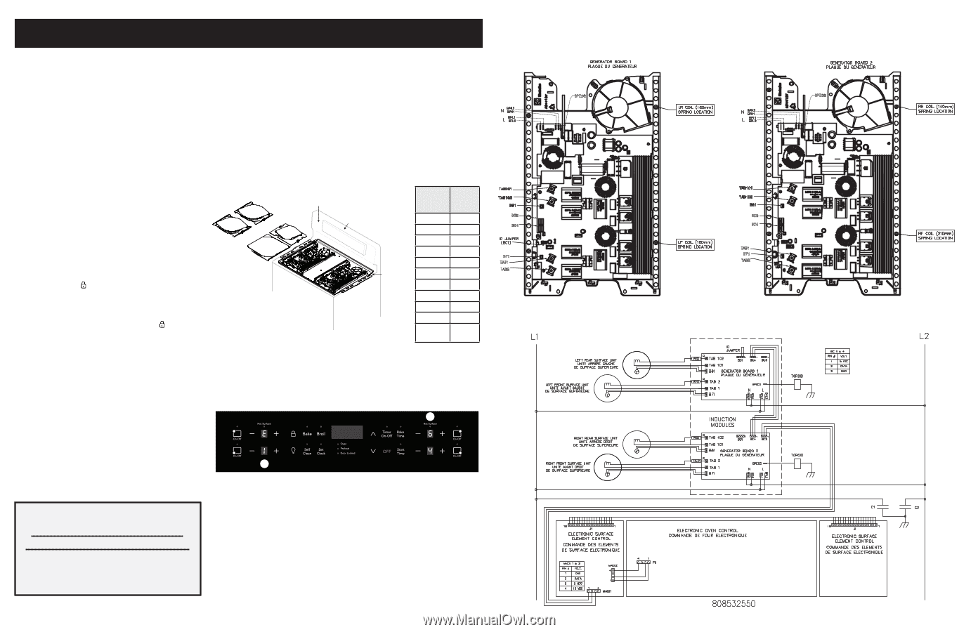
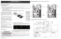
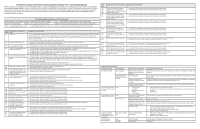
SERVICE DATA SHEET Electric Ranges with ES3000 and Induction Smoothtop NOTICE - This service data sheet is intended for use by persons having electrical and mechanical training and a level of knowledge of these subjects generally considered acceptable in the appliance repair trade. The manufacturer cannot be responsible, nor assume any liability for injury or damage of any kind arising from the use of this data sheet. SAFE SERVICING PRACTICES To avoid the possibility of personal injury and/or property damage, it is important that safe servicing practices be observed. The following are examples, but without limitation, of such practices. 1. Before servicing or moving an appliance remove power cord from electrical outlet, trip circuit breaker to OFF, or remove fuse. 2. Never interfere with the proper installation of any safety device. 3. GROUNDING: The standard color coding for safety ground wires is GREEN or GREEN WITH YELLOW STRIPES. Ground leads are not to be used as current carrying conductors. It is extremely important that the service technician reestablish all safety grounds prior to completion of service. Failure to do so will create a potential safety hazard. 4. Prior to returning the product to service, ensure that: • All electric connections are correct and secure. • All electrical leads are properly dressed and secured away from sharp edges, high-temperature components, and moving parts. • All uninsulated electrical terminals, connectors, heaters, etc. are adequately spaced away from all metal parts and panels. • All safety grounds (both internal and external) are correctly and securely reassembled. Electronic Surface Element Control (ESEC) This range is equipped with an Electronic Surface Element Control (ESEC), which precisely controls the smoothtop cooking elements at multiple settings. For the user, the elements are operated by pressing the touch pads located on the control panel for the desired settings. The control settings are shown in 1-digit displays. LF Coil LR Coil RR Coil RF Coil Control Panel Assembly Electronic oven/cooktop control (EOC) Displayed Power Level L 2 3 4 Power Level % 4.0 5.5 10.5 15.5 Hot Surface indication - If any of the induction elements are hot, a hot surface light will remain ON until the cooktop cools. ESEC lockout feature - The electronic oven control's selfclean and Cooktop Lockout features will not operate when a surface element is ON. Conversely, the surface elements controlled by the ESEC will not operate when an oven control self-clean or Cooktop Lockout mode is active. When the oven control is in a self-clean or Cooktop Lockout mode, will appear in the oven control display to signify that the surface heating elements are locked out. Induction control assembly 5 21.0 6 31.0 7 45.0 8 54.0 9 64.0 H 100.0 P 156- 164 ESEC system components The ESEC system consists of the following components: ES3000 oven/cooktop control (EOC) - circuit boards mounted in plastic chassis. Induction control assembly - circuit boards in plastic housings mounted under the cooktop on a metal tray with six screws. Notes on replacing parts Replacing an induction generator board - When replacing an induction generator board under the cooktop, do not over-tighten the 2 screws that secure each board to the range. Over-tightening the screws can damage the plastic housings holding the circuit boards. Replacing an induction element Ensure correct coil location. IMPORTANT DO NOT REMOVE THIS BAG OR DESTROY THE CONTENTS WIRING DIAGRAMS AND SERVICE INFORMATION ENCLOSED REPLACE CONTENTS IN BAG Error notification in an induction system Induction related alarms are displayed using all 4 displays of the user interface. The Rear Left display is used to notify the user that the message being displayed is an error and is represented with an "E" in the display. The Front Left display is used to show which induction generator board is generating the error. 2 1 1. The Front Left display showing "1" above indicates that the left generator board is producing the error. If display shows a "2", this indicates that the right generator board is producing the error. If display shows a "0", this indicates that the issue was generated by the cooktop control and not the induction generator. 2. The Front Right and Rear Right displays display the actual error. An example of a stuck cooling fan on the left induction generator board (E164) is shown above. Replacing the ES3000 control* - When replacing the oven/cooktop control in the backguard, DO NOT over tighten the screws that secure it. Upper and lower support brackets should be reinstalled. * Please note: Electronic boards are very sensitive to static electricity. Static electricity can permanently damage electronic boards. Before handling these parts, be sure to drain static electricity from your body by properly grounding yourself. SCHEMATIC DIAGRAM - Induction Controls Wiring/Connections SCHEMATIC DIAGRAM - ESEC with Induction Cooktop 808533905 Rev B (17/11)
-
 1
1 -
 2
2 -
 3
3 -
 4
4
 |
 |