Frigidaire FFRA2822U2 Installation Instructions - Page 7
Thru-The-Wall Installation
 |
View all Frigidaire FFRA2822U2 manuals
Add to My Manuals
Save this manual to your list of manuals |
Page 7 highlights
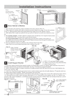
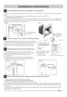
Installation Instructions Thru-The-Wall Installation NOTE: Consult local building codes prior to installation, or a qualified carpenter. 1 Select Wall Location This air conditioner slides out from its cabinet, so that it can be installed through an outside wall as explained below. BY BN Max wall thickness 8" 8.25" NOTE: IMPORTANT: Side louvers must never be blocked. All parts needed for Thru-The-Wall Installation are provided, except a wood frame, shims, and 10 wood screws (#10-1" long minimum). Select a wall surface that: 1. Does not support major structural loads such as the frame construction at ends of windows, and under truss-bearing points, etc. 2. Does not have plumbing or wiring inside. 3. Is near existing electrical outlets, or where another outlet can be installed. 4. Faces to the area to be cooled, and it is not blocked. 5. Allows unblocked airflow from rear sides and end (outside) of installed air conditioner. 2 Prepare Wall 1. Prepare wall in frame construction (including brick and stucco veneer). Working from inside the room, find wall stud nearest the center of area where air conditioner will be installed (by sounding wall, or by magnetically finding nails). 2. Cut out a hole on each side of center stud. 3. Measure between inside edges of every other stud as shown in FIG.1. Carefully measure and cut an opening with the following dimensions depending on your model. See FIG.1 and FIG.2. WIDTH "X" = inside model width plus twice the thickness of framing material used. HEIGHT "Y" = inside model height plus twice the thickness of framing material used. Capacity: Inside Frame Height: BY 15,000~18,500BTU 18" (45.7 cm) BN 22,000~28,500BTU 18-7/8" (47.9 cm) Inside Frame Width: 23-7/8" (60.6 cm) 26-3/4" (67.9 cm) FIG.1 FIG.2 3-3/8" MIN (8.6 cm) Y Inside Frame Height Inside Frame Width X UP TO 8-1/2" 7
-
 1
1 -
 2
2 -
 3
3 -
 4
4 -
 5
5 -
 6
6 -
 7
7 -
 8
8 -
 9
9
 |
 |