Frigidaire FGGS3045KF Installation Instructions (All Languages) - Page 1
Frigidaire FGGS3045KF - 30' Gas Slide-In Lery SS Group Manual
 |
UPC - 057112102955
View all Frigidaire FGGS3045KF manuals
Add to My Manuals
Save this manual to your list of manuals |
Page 1 highlights
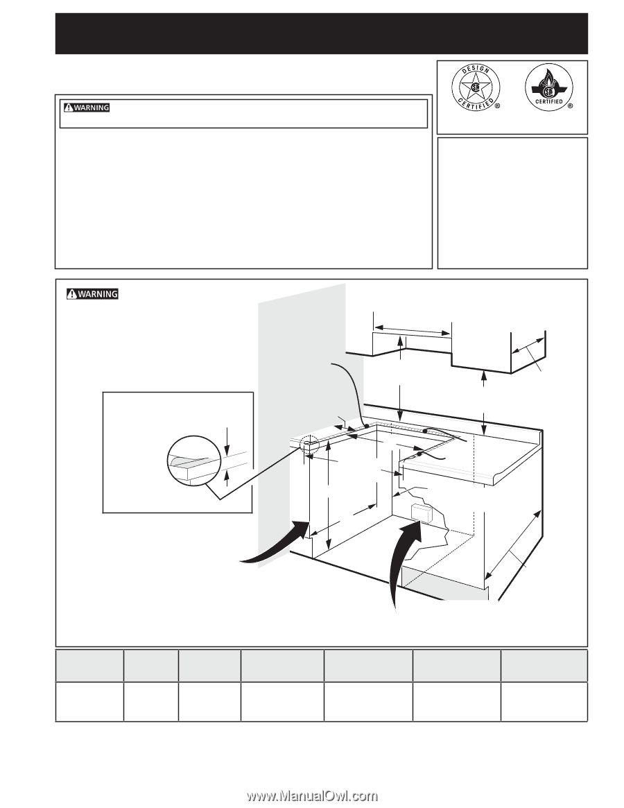
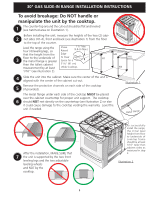
30" GAS SLIDE-IN RANGE INSTALLATION INSTRUCTIONS INSTALLATION AND SERVICE MUST BE PERFORMED BY A QUALIFIED INSTALLER. IMPORTANT: SAVE FOR LOCAL ELECTRICAL INSPECTOR'S USE. READ AND SAVE THESE INSTRUCTIONS FOR FUTURE REFERENCE. If the information in this manual is not followed exactly, a fire or explosion may result causing property damage, personal injury or death. FOR YOUR SAFETY: - Do not store or use gasoline or other flammable vapors and liquids in the vicinity of this or any other appliance. - WHAT TO DO IF YOU SMELL GAS: • Do not try to light any appliance. • Do not touch any electrical switch; do not use any phone in your building. • Immediately call your gas supplier from a neighbor's phone. Follow the gas supplier's instructions. • If you cannot reach your gas supplier, call the fire department. - Installation and service must be performed by a qualified installer, service agency or the gas supplier. Refer to your serial plate for applicable agency certification Appliances Installed in the state of Massachusetts: This Appliance can only be installed in the state of Massachusetts by a Massachusetts licensed plumber or gasfitter. This appliance must be installed with a three (3) foot / 36 in. long flexible gas connector. A"T" handle type manual gas valve must be installed in the gas supply line to this appliance. Do not install the unit in the cabinet before reading next page. WALL 30" Min. (76.2 cm Min.) These surfaces should be flat & leveled (hatched area). 30" Min. (76.2 cm) Min. (see Note 3) Shave Raised 1 ½" Max. (3.8 cm Max.) 5" Min. (12.7 cm Min.) From Wall Both Sides 18" Min. (45.7 cm) Min. Edge to Clear E 1/4" min. Space 31 1/2" 1/2" min. for a 31½" (81 cm) Wide Cooktop. (81 cm) Exact G Approx. 1 7/8" (4.8 cm) F 13" (33 cm) Locate Cabinet Doors 1" (2.5 cm) Min. from Cutout Opening. 24" Min. (61 cm Min.) Grounded Jonction Box or Wall Outlet Should Be Located 8" to 17" (20.3 cm to 43.2 cm) From Right Cabinet and 2" to 4" (5.1 cm to 10.2 cm) From Floor. A. HEIGHT B. WIDTH (Under Cooktop) C. COOKTOP WIDTH 35 7/8" (91,1 cm) 30" (76,2 cm) 36 5/8" (93 cm) 31 1/2" (80 cm) D. TOTAL DEPTH TO FRONT OF RANGE 28 5/16" (71,9 cm) E. CUTOUT WIDTH*** (Countertop and cabinet) 30±1/16" (76,2±0,15 cm) NOTE: Wiring diagram for these appliances are enclosed in this booklet. Printed in United States 1 F. CUTOUT DEPTH G. HEIGHT OF COUNTERTOP 21 3/4" (55,2 cm) Min. 22 1/8" (56,2 cm) Max 24" (61 cm) Min. with backguard 35 7/8" (91,1 cm) Min. 36 5/8" (93 cm) Max. P/N 318201691 (1007) Rev. A English - pages 1-11; Español - páginas 12-22; Français - pages 23-33; Notes 34-35; Wiring diagrams - Pages 36
-
 1
1 -
 2
2 -
 3
3 -
 4
4 -
 5
5 -
 6
6 -
 7
7 -
8
-
9
-
10
-
11
-
12
-
13
-
14
-
15
-
16
-
17
-
18
-
19
-
20
-
21
-
22
-
23
-
24
-
25
-
26
-
27
-
28
-
29
-
30
-
31
-
32
-
33
-
34
-
35
-
36
 |
 |