Frigidaire FGGS3045KF Installation Instructions (All Languages) - Page 6
Provide an adequate Gas Supply, Seal the openings, Connect the range to the gas, supply - installation manual
 |
UPC - 057112102955
View all Frigidaire FGGS3045KF manuals
Add to My Manuals
Save this manual to your list of manuals |
Page 6 highlights
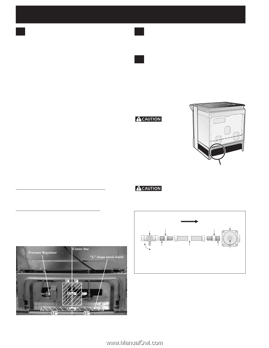
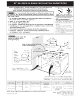
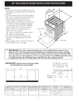
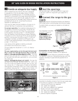
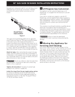
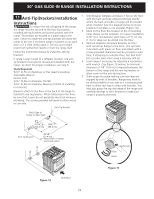
30" GAS SLIDE-IN RANGE INSTALLATION INSTRUCTIONS 3 Provide an adequate Gas Supply When shipped from the factory, this unit is designed to operate on 4"(10,16 cm) water column (1.0 kPa) Natural gas manifold pressure. A convertible pressure regulator is connected to the range manifold and MUST be connected in series with the gas supply line. If LP/ Propane conversion kit has been used, follow instructions provided with the kit for converting the pressure regulator to LP/Propane use. Care must be taken during installation of range not to obstruct the flow of combustion and ventilation air. For proper operation, the maximum inlet pressure to the regulator should be no more than 14"(35,56 cm) of water column pressure (3.5 kPa). The inlet pressure to the regulator must be at least 1" (.25 kPa) greater than the regulator manifold pressure setting. Examples: If regulator is set for natural gas 4"(10,16 cm) manifold pressure, inlet pressure must be at least 5"(12.60 cm); if regulator has been converted for LP/Propane gas 10"(25,4 cm) manifold pressure, inlet pressure must be at least 11"(27,9 cm). Leak testing of the appliance shall be conducted according to the instructions in step 5. The gas supply line should be ½" or ¾" I.D. (Interior Diameter). The gas supply piping can be through the back wall (Fig. 3, zone 1) or through the floor (Fig. 3, zone 2): Zone 1 - Through the Back Wall (7" X 6") - The best place to have your gas line in is between 1" (2.5 cm) and 8" (20.3cm) from the floor and within 3" (7.6 cm) from the center line. Zone 2 - Through the Floor (~2" X 24") - The gas line can also come through the floor within 12" (30.5 cm) from the center line against the back wall. In case, you can remove the "L" shape piece of metal at the bottom metal portion at the back of the unit. There is absolutely no problem removing this "L" shape piece of metal, it is there to protect the gas line especially during transport. 4 Seal the openings Seal any openings in the wall behind the range and in the floor under the range after gas supply line is installed. 5 Connect the range to the gas supply Important: Remove all packing material and literature from range before connecting gas and electrical supply. To prevent leaks, put pipe joint sealant on all external pipe threads. Your regulator is located as shown in figure 4. Do not allow regulator to rotate on pipe when tightening fittings. Figure 4 Pressure regulator location Connection to Pressure Regulator The regulator is already installed on the appliance. Do not make the connection too tight. The regulator is die cast. Overtightening may crack the regulator resulting in a gas leak and possible fire or explosion. Manual Shutoff Valve Flare Union GAS FLOW Pressure Flare Regulator Union On Nipple Off Flexible Connector Nipple Access Cap All connections must be wrench-tightened Figure 5 Figure 3 Assemble the flexible connector from the gas supply pipe to the pressure regulator in the following order: 1. manual shutoff valve (not supplied) 2. 1/2" nipple (not supplied) 3. 1/2" flare union adapter (not supplied) 4. flexible connector (not supplied) 5. 1/2" flare union adapter (not supplied) 6. 1/2" nipple (not supplied) 7. pressure regulator (supplied) 6
-
 1
1 -
 2
2 -
 3
3 -
 4
4 -
 5
5 -
 6
6 -
 7
7 -
 8
8 -
 9
9 -
 10
10 -
 11
11 -
 12
12 -
13
-
14
-
15
-
16
-
17
-
18
-
19
-
20
-
21
-
22
-
23
-
24
-
25
-
26
-
27
-
28
-
29
-
30
-
31
-
32
-
33
-
34
-
35
-
36
 |
 |