Frigidaire FGMV185KF Installation Instructions (All Languages) - Page 4
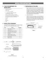
Ventilation System
 |
UPC - 012505560231
View all Frigidaire FGMV185KF manuals
Add to My Manuals
Save this manual to your list of manuals |
Page 4 highlights
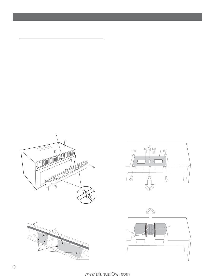
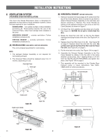
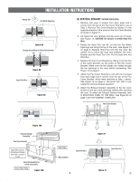
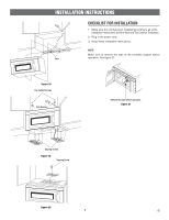
INSTALLATION INSTRUCTIONS 8 VENTILATION SYSTEM (PREPARING OVEN FOR INSTALLATION) This Over the Range Microwave Oven is designed for adaptation to three types of hood ventilation systems. Select the type required for your installation. RECIRCULATING - non-vented, ductless. Follow installation procedure (A). Recirculating requires the use of the Charcoal Filters, which have already been installed in the oven. HORIZONTAL EXHAUST - outside ventilation. Follow installation procedure (B). VERTICAL EXHAUST - outside ventilation. Follow installation procedure (C). (A) RECIRCULATING: NON-VENTED, DUCTLESS OPERATION The unit is shipped assembled for recirculating. NOTE: 1. The Exhaust Damper Assembly is not required for recirculating exhaust. 2. The Charcoal Filters should be replaced every 6 to 12 months, depending on use. Oven Light Cover Oven Light (B) HORIZONTAL EXHAUST: OUTSIDE VENTILATION 1. Remove 3 screws from back edge and 5 screws from the top of Fan Cover Bracket. Save 3 screws to use them to attach Exhaust Damper Assembly to the wall later and discard remaining 5. Remove Fan Cover Bracket by sliding it in the opposite direction of the arrow on the Fan Cover Bracket, as shown in Figure 7. 2. Lift Hood Fan Unit carefully and slip wires out of cavity. See Figure 8. CAUTION: Do not pull or stretch Hood Fan Wire. 3. Rotate the Hood Fan Unit 180˚ so that the Fan Blade Openings are facing the back of the oven. See Figure 9A on page 5. 4. Replace Hood Fan Wire from (A) to (B). See Figure 9B on page 5. Replace Hood Fan Unit into the oven. Be careful not to pinch the Hood Fan Wire and the Hood Fan Unit. See Figure 9C on page 5. 5. Put the wire back into cavity. See Figure 10A on page 5. 6. Assemble the Exhaust Damper Assembly to the Fan Cover Bracket by sliding it into the slits in the same direction as the arrow. Use 1 Tapping Screw 4 x 8 mm from the INSTALLATION HARDWARE and tighten into place. See Figure 10B on page 5. 7. This assembly will be mounted to the Outside Rear Exhaust cutout in future instructions. See WALL TEMPLATE for further procedures. Fan Cover Bracket Hood Louver Figure 6A Hood Louver (Inside) Charcoal Filters Upper Tab Figure 7 Hood Fan Wire Hood Fan Unit Tabs Figure 6B E 4 Figure 8
-
 1
1 -
 2
2 -
 3
3 -
 4
4 -
 5
5 -
 6
6 -
 7
7 -
 8
8 -
 9
9 -
 10
10 -
11
-
12
-
13
-
14
-
15
-
16
-
17
-
18
-
19
-
20
-
21
-
22
-
23
-
24
 |
 |