Frigidaire FGMV185KF Installation Instructions (All Languages) - Page 6
Oven Installation
 |
UPC - 012505560231
View all Frigidaire FGMV185KF manuals
Add to My Manuals
Save this manual to your list of manuals |
Page 6 highlights
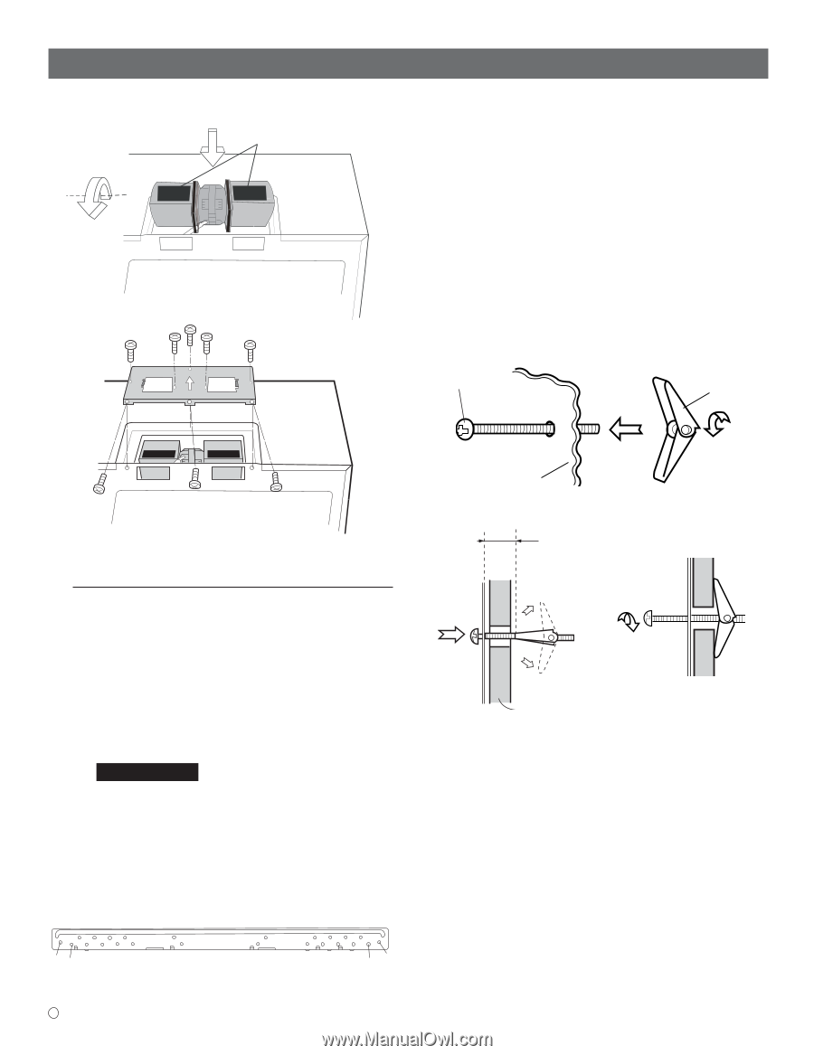
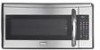
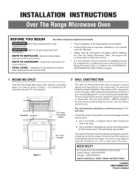
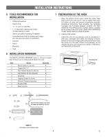
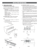
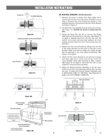
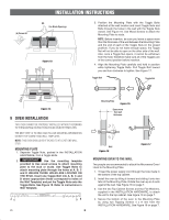
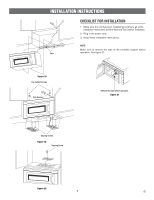
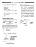
(A) Rotate 90° INSTALLATION INSTRUCTIONS (B) Fan Blade Openings Figure 13 3. Position the Mounting Plate with the Toggle Bolts attached at the wall location and insert Toggle Nuts and Bolts through the holes in the wall with the Toggle Nuts closed. See Figure 16. Use Wood Screws to attach the Mounting Plate to studs. NOTE: Before insertion, be sure you leave a space more than the thickness of the wall between the Mounting Plate and the end of each of the Toggle Nuts (in the closed position). If you do not leave enough space, the Toggle Nut will not be able to open on the other side of the wall. Also, once a Toggle Nut opens, it cannot be withdrawn from the hole; therefore make sure all of the Toggles are in the correct position before insertion. 4. Align the Mounting Plate carefully and hold in position while tightening Toggle Bolts. Pull Toggle Bolt toward you and turn clockwise to tighten. See Figure 17. Toggle Bolt Toggle Nut Figure 14 9 OVEN INSTALLATION THIS OVEN CANNOT BE PROPERLY INSTALLED WITHOUT REFERRING TO THE MOUNTING INSTRUCTIONS FOUND ON BOTH TEMPLATES. THE NEXT STEP IS TO READ AND FOLLOW MOUNTING INFORMATION ON BOTH TOP CABINET AND WALL TEMPLATES. NOTE: THIS OVEN SHOULD BE ATTACHED TO AT LEAST ONE WALL STUD. MOUNTING PLATE 1. Separate Toggle Nuts, packed in the INSTALLATION HARDWARE, from 4 Toggle Bolts. 2. IMPORTANT Use the mounting template provided to Use wood screws to attach mounting plate to the stud or studs. Use Toggle Bolts to attach mounting plate through the holes at A, B, C and D UNLESS THOSE HOLES ARE LOCATED ON THE STUD. Insert one Toggle Bolt into A, B, C and D where appropriate (these correspond to holes of the Wall Template) and put the Toggle Nuts onto the Toggle Bolts. See Figure 15. Refer to instructions in Wall Template. AC SUITABLE FOR USE ABOVE GAS OR ELECTRICAL COOKING EQUIPMENT 36 INCHES OR LESS WIDE WARNING TO REDUCE THE RISK OF FIRE AND ELECTRICAL SHOCK,INSTALL AT LEAST 13-3/16 INCHES ABOVE A RANGE (OR COOK TOP) DB E 6 Mounting Plate Figure 15 Space more than wall thickness Wall Figure 16 Figure 17 MOUNTING OVEN TO THE WALL Two people are recommended to attach the Microwave Oven/ Hood to the Mounting Plate. 1. Thread the power supply cord through the hole made in the bottom of the top cabinet. 2. Install the oven by tilting it forward and sliding it onto two tabs of the Mounting Plate. Rotate the oven up so it rests against the wall. See Figure 18 on page 7. 3. Use the two Top Cabinet Screws and two Flat Washers, supplied in the INSTALLATION HARDWARE, to attach the unit to the top cabinet. See Figure 19 on page 7. 4. Secure the bottom of the oven to the Mounting Plate by using two Tapping Screws 4 x 8 mm from the INSTALLATION HARDWARE. See Figure 19 on page 7.
-
 1
1 -
 2
2 -
 3
3 -
 4
4 -
 5
5 -
 6
6 -
 7
7 -
 8
8 -
 9
9 -
 10
10 -
 11
11 -
 12
12 -
13
-
14
-
15
-
16
-
17
-
18
-
19
-
20
-
21
-
22
-
23
-
24
 |
 |