Frigidaire PLGF659GC Wiring Diagram (All Languages) - Page 3
Cooling Fan, Circuit Analysis Matrix
 |
UPC - 057112098968
View all Frigidaire PLGF659GC manuals
Add to My Manuals
Save this manual to your list of manuals |
Page 3 highlights
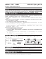
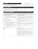
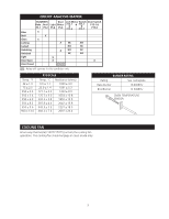
CIRCUIT ANALYSIS MATRIX Bake ELEMENTS Bake Broil P5-1 P5-2 X Light P5-8 Door Motor P5-6 Lock Motor Switch Door Switch P15-1 A P15-1 & & P15-2 P15-7 P15-1 & P15-3 Broil X Clean X Locking X NC NO Locked NO NC Unlocking Unlocked X NO NC NC NO Light X Door Open X X Door Closed Relay will operate in this condition only Temp. °F 32 ± 1.9 75 ± 2.5 250 ± 4.4 350 ± 5.4 450 ± 6.9 550 ± 8.2 650 ± 9.6 900 ± 13.6 RTD SCALE Temp. °C 0.0 ± 1.1 23.9 ± 1.4 121.1 ± 2.4 176.7 ± 3.0 232.2 ± 3.8 287.8 ± 4.6 343.3 ± 5.3 482.2 ± 7.6 Resistance (ohms) 1000 ± 4.0 1091 ± 5.3 1453 ± 8.9 1654 ± 10.8 1852 ± 13.5 2047 ± 15.8 2237 ± 18.5 2697 ± 24.4 BURNER RATING Rating See nameplate Bake Burner 16 000BTU Broil Burner 12 500BTU OVEN TEMPERATURE SENSOR COOLING FAN A two way thermostat (140°F/170°F) controls the cooling fan operation. The cooling fan should engage in clean mode only. 3
-
 1
1 -
 2
2 -
 3
3 -
 4
4
 |
 |
