Fujitsu Fi-4750c Operation Manual - Page 33
REPLACEMENT, OF PARTS, Attach the Pad Assembly
 |
UPC - 097564303531
View all Fujitsu Fi-4750c manuals
Add to My Manuals
Save this manual to your list of manuals |
Page 33 highlights
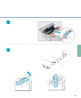
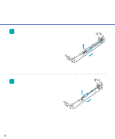
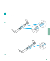
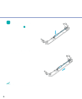
REPLACEMENT OF PARTS 3 Slide the Pad Assembly to the left and pull it towards you. Then, being careful not to hook the spring for the Pad, remove the Pad Assembly. NOTE Hold both ends of the Pad assembly as shown in the right photo. CAUTION Don't hold the sensor arm with the Pad assembly. Pad assembly 4 Attach the Pad Assembly to the ADF in the reverse sequence of step 3. NOTE Fit the Pad assembly pin into the larger hole, then slide it to the right until it stops. 5 Close the ADF. 3-3
-
 1
1 -
2
-
3
-
4
-
5
-
6
-
7
-
8
-
9
-
10
-
11
-
12
-
13
-
14
-
15
-
16
-
17
-
18
-
19
-
20
-
21
-
22
-
23
-
24
-
25
-
26
-
27
-
 28
28 -
 29
29 -
 30
30 -
 31
31 -
 32
32 -
 33
33 -
 34
34 -
 35
35 -
 36
36 -
 37
37 -
 38
38 -
39
-
40
-
41
-
42
-
43
-
44
-
45
-
46
-
47
-
48
-
49
-
50
-
51
-
52
-
53
-
54
-
55
-
56
-
57
-
58
-
59
-
60
-
61
 |
 |

3-3
REPLACEMENT
OF PARTS
Pad assembly
3
Slide the Pad Assembly to the
left and pull it towards you.
Then, being careful not to hook
the spring for the Pad, remove
the Pad Assembly.
NOTE
Hold both ends of the Pad assembly as shown
in the right photo.
CAUTION
Don’t hold the sensor arm with the Pad
assembly.
4
Attach the Pad Assembly to
the ADF in the reverse
sequence of step 3.
NOTE
Fit the Pad assembly pin into the larger hole,
then slide it to the right until it stops.
5
Close the ADF.