Fujitsu MAN3367MC Manual/User Guide - Page 17

TABLES, SCSI connector SCA2 type LVD 16-bit SCSI

Page 17 highlights

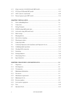
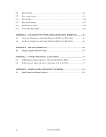
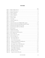
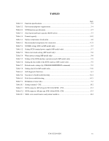
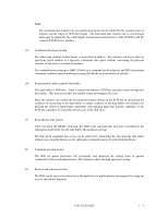
TABLES page Table 2.1 Function specifications ...2-2 Table 2.2 Environmental/power requirements 2-4 Table 2.3 SCSI function specifications ...2-7 Table 3.1 Zone layout and track capacity (MAN series 3-3 Table 3.4 Format capacity...3-10 Table 4.1 Surface temperature check point 4-6 Table 4.2 Recommended components for connection 4-21 Table 5.1 SCSI ID setting (CN2 on MP model only 5-7 Table 5.2 Setting SCSI terminal power supply (MP model only 5-7 Table 5.3 Motor start mode setting (MP model only 5-8 Table 5.4 Write protect setting (MP model only 5-8 Table 5.5 Setting of the SCSI interface operation mode (MP model only 5-9 Table 5.6 Setting the bus width of the SCSI interface (MP model only 5-9 Table 5.7 Default mode settings (by CHANGE DEFINITION command 5-9 Table 5.8 Setting check list (MP model only 5-10 Table 6.1 Self-diagnostic functions...6-1 Table 6.2 System-level field troubleshooting 6-14 Table 6.3 Disk drive troubleshooting...6-15 Table 7.1 Definition of sense data...7-3 Table B.1 Setting terminal: CN2 ...B-2 Table C.1 SCSI connector (SCA2 type LVD 16-bit SCSI): CN1 C-2 Table C.2 SCSI connector (68 pin type LVD 16-bit SCSI): CN1 C-3 Table D.1 MAN series model names and product numbers D-2 C141-E128-01EN xv

  • 1
  • 2
  • 3
  • 4
  • 5
  • 6
  • 7
  • 8
  • 9
  • 10
  • 11
  • 12
  • 13
  • 14
  • 15
  • 16
  • 17
  • 18
  • 19
  • 20
  • 21
  • 22
  • 23
  • 24
  • 25
  • 26
  • 27
  • 28
  • 29
  • 30
  • 31
  • 32
  • 33
  • 34
  • 35
  • 36
  • 37
  • 38
  • 39
  • 40
  • 41
  • 42
  • 43
  • 44
  • 45
  • 46
  • 47
  • 48
  • 49
  • 50
  • 51
  • 52
  • 53
  • 54
  • 55
  • 56
  • 57
  • 58
  • 59
  • 60
  • 61
  • 62
  • 63
  • 64
  • 65
  • 66
  • 67
  • 68
  • 69
  • 70
  • 71
  • 72
  • 73
  • 74
  • 75
  • 76
  • 77
  • 78
  • 79
  • 80
  • 81
  • 82
  • 83
  • 84
  • 85
  • 86
  • 87
  • 88
  • 89
  • 90
  • 91
  • 92
  • 93
  • 94
  • 95
  • 96
  • 97
  • 98
  • 99
  • 100
  • 101
  • 102
  • 103
  • 104
  • 105
  • 106
  • 107
  • 108
  • 109
  • 110
  • 111
  • 112
  • 113
  • 114
  • 115
  • 116
  • 117
  • 118
  • 119
  • 120
  • 121
  • 122
  • 123
  • 124
  • 125
  • 126
  • 127
  • 128
  • 129
  • 130
  • 131
  • 132
  • 133
  • 134
  • 135
  • 136
  • 137
  • 138
  • 139
  • 140
  • 141
  • 142
  • 143
  • 144
  • 145

C141-E128-01EN
xv
TABLES
page
Table 2.1
Function specifications
............................................................................................................
2-2
Table 2.2
Environmental/power requirements
.........................................................................................
2-4
Table 2.3
SCSI function specifications
....................................................................................................
2-7
Table 3.1
Zone layout and track capacity (MAN series)
.........................................................................
3-3
Table 3.4
Format capacity
......................................................................................................................
3-10
Table 4.1
Surface temperature check point
..............................................................................................
4-6
Table 4.2
Recommended components for connection
...........................................................................
4-21
Table 5.1
SCSI ID setting (CN2 on MP model only)
..............................................................................
5-7
Table 5.2
Setting SCSI terminal power supply (MP model only)
............................................................
5-7
Table 5.3
Motor start mode setting (MP model only)
..............................................................................
5-8
Table 5.4
Write protect setting (MP model only)
....................................................................................
5-8
Table 5.5
Setting of the SCSI interface operation mode (MP model only)
.............................................
5-9
Table 5.6
Setting the bus width of the SCSI interface (MP model only)
.................................................
5-9
Table 5.7
Default mode settings (by CHANGE DEFINITION command)
.............................................
5-9
Table 5.8
Setting check list (MP model only)
........................................................................................
5-10
Table 6.1
Self-diagnostic functions
..........................................................................................................
6-1
Table 6.2
System-level field troubleshooting
........................................................................................
6-14
Table 6.3
Disk drive troubleshooting
.....................................................................................................
6-15
Table 7.1
Definition of sense data
............................................................................................................
7-3
Table B.1
Setting terminal:
CN2
............................................................................................................
B-2
Table C.1
SCSI connector (SCA2 type LVD 16-bit SCSI):
CN1
...........................................................
C-2
Table C.2
SCSI connector (68 pin type LVD 16-bit SCSI):
CN1
..........................................................
C-3
Table D.1
MAN series model names and product numbers
....................................................................
D-2