Fujitsu MHW2080AT Manual/User Guide - Page 10
Jumper Settings
 |
View all Fujitsu MHW2080AT manuals
Add to My Manuals
Save this manual to your list of manuals |
Page 10 highlights
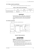
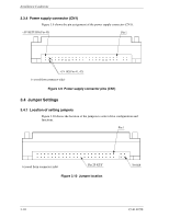
Installation Conditions 3.3.4 Power supply connector (CN1) Figure 3.9 shows the pin assignment of the power supply connector (CN1). Figure 3.9 Power supply connector pins (CN1) 3.4 Jumper Settings 3.4.1 Location of setting jumpers Figure 3.10 shows the location of the jumpers to select drive configuration and functions. Figure 3.10 Jumper location 3-10 C141-E250
-
 1
1 -
2
-
3
-
4
-
 5
5 -
 6
6 -
 7
7 -
 8
8 -
 9
9 -
 10
10 -
 11
11 -
 12
12 -
 13
13 -
 14
14
 |
 |
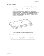
Installation Conditions
3.3.4
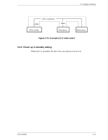
Power supply connector (CN1)
Figure 3.9 shows the pin assignment of the power supply connector (CN1).
Figure 3.9
Power supply connector pins (CN1)
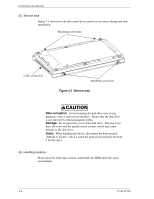
3.4
Jumper Settings
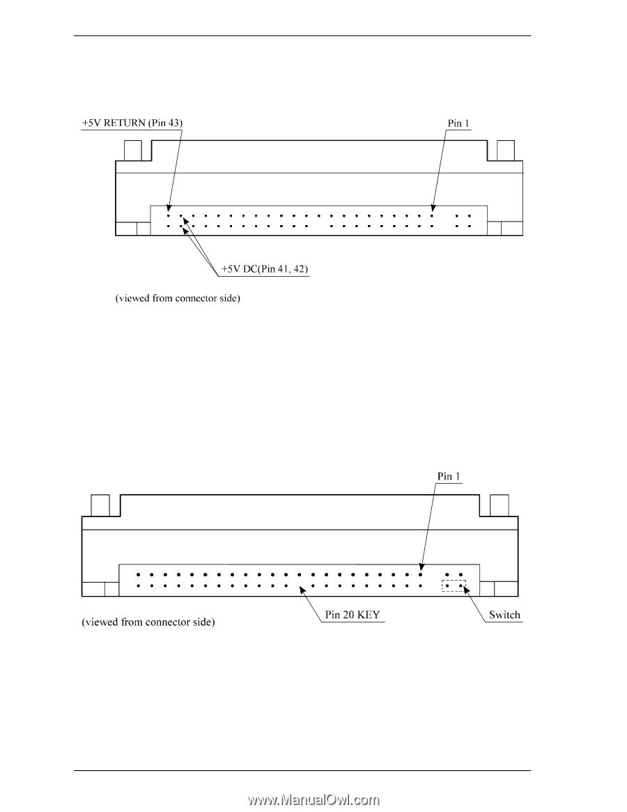
3.4.1
Location of setting jumpers
Figure 3.10 shows the location of the jumpers to select drive configuration and
functions.
Figure 3.10
Jumper location
3-10
C141-E250