Fujitsu MHW2080AT Manual/User Guide - Page 9
Cable connector specifications, Device connection - power
 |
View all Fujitsu MHW2080AT manuals
Add to My Manuals
Save this manual to your list of manuals |
Page 9 highlights
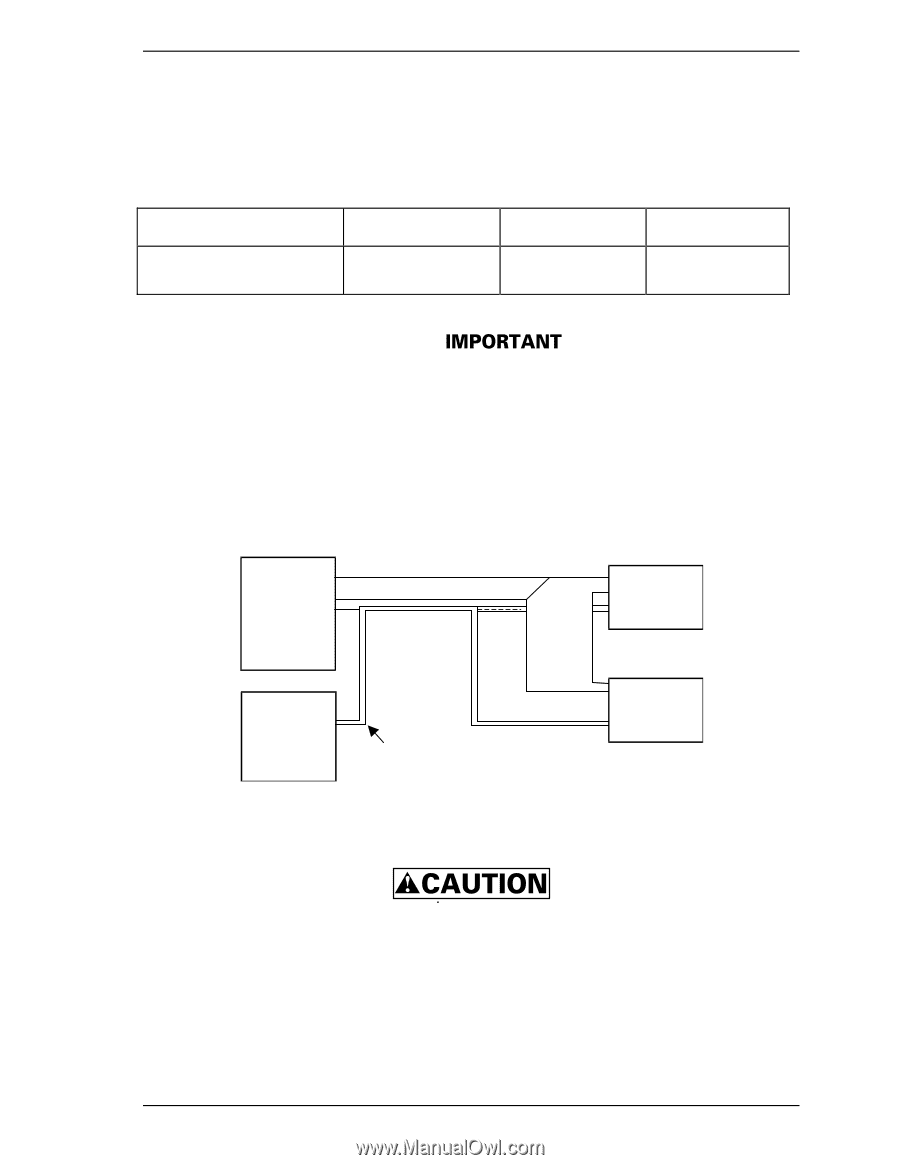
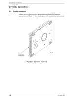
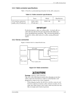
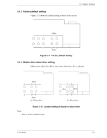
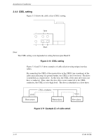
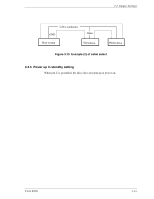
3.3 Cable Connections 3.3.2 Cable connector specifications Table 3.2 lists the recommended specifications for the cable connectors. Table 3.2 Cable connector specifications ATA interface and power supply cable (44-pin type) Name Cable socket (44-pin type) Model 89361-144 Manufacturer FCI For the host interface cable, use a ribbon cable. A twisted cable or a cable with wires that have become separated from the ribbon may cause crosstalk between signal lines. This is because the interface is designed for ribbon cables and not for cables carrying differential signals. 3.3.3 Device connection Figure 3.8 shows how to connect the devices. Host system ATA-cable Disk Drive #0 ATA-cable DC Power supply Power supply cable Disk Drive #1 Figure 3.8 Cable connections C141-E250 Damage: Interface cable connection Take note of the following precaution about plugging an interface cable (socket) into the interface connector of the disk drive and plugging the connector into a host receptacle: − When plugging together the disk drive interface connector and the host receptacle or interface cable connector (socket), do not apply more than 10 kgf of force in the connection direction once they are snugly and securely in position. 3-9
-
 1
1 -
2
-
3
-
 4
4 -
 5
5 -
 6
6 -
 7
7 -
 8
8 -
 9
9 -
 10
10 -
 11
11 -
 12
12 -
 13
13 -
 14
14
 |
 |