Fujitsu MHW2080AT Manual/User Guide - Page 3
Mounting - specification
 |
View all Fujitsu MHW2080AT manuals
Add to My Manuals
Save this manual to your list of manuals |
Page 3 highlights
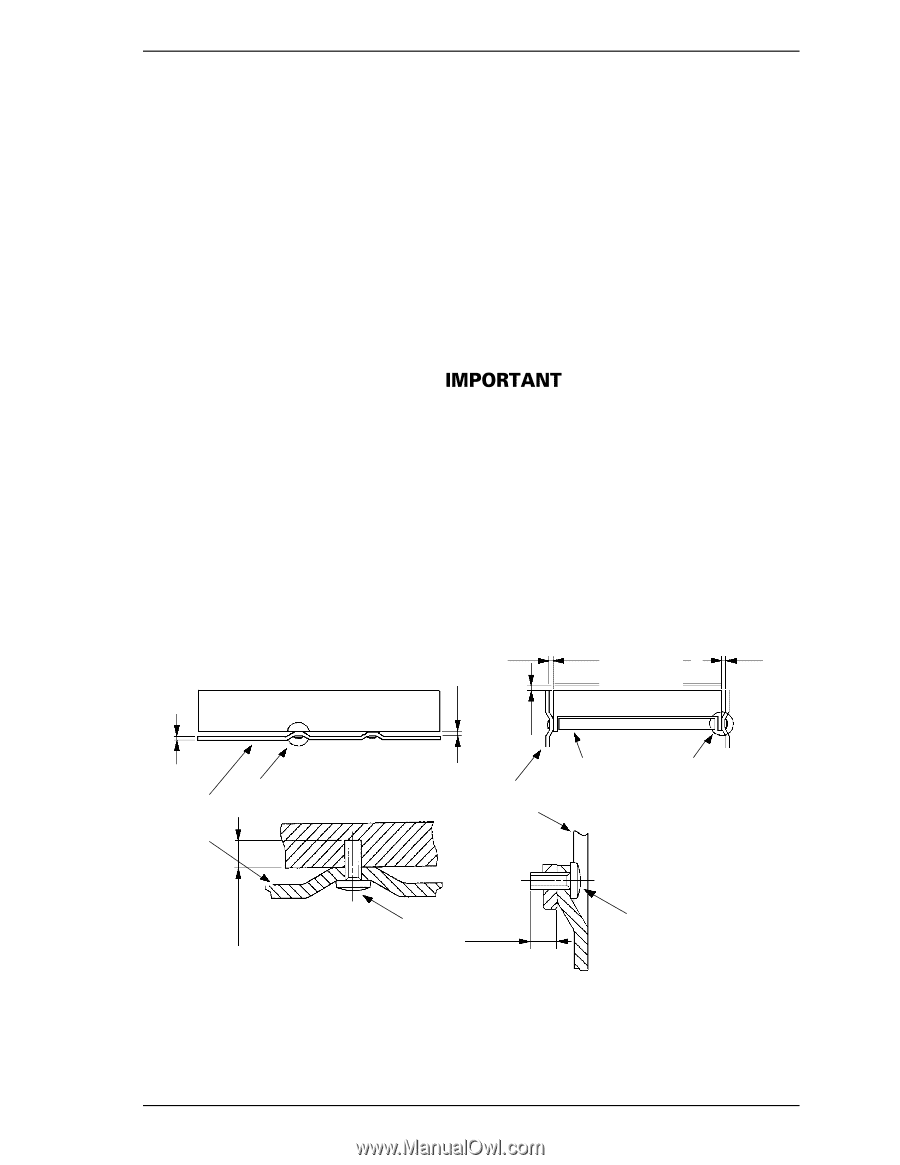
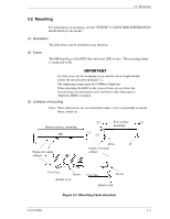
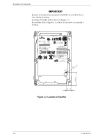
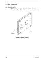
3.2 Mounting 3.2 Mounting For information on mounting, see the "FUJITSU 2.5-INCH HDD INTEGRATION GUIDANCE (C141-E144)." (1) Orientation The disk drives can be mounted in any direction. (2) Frame The MR head bias of the HDD disk enclosure (DE) is zero. The mounting frame is connected to SG. Use M3 screw for the mounting screw and the screw length should satisfy the specification in Figure 3.2. The tightening torque must be 0.49N•m (5kgf•cm). When attaching the HDD to the system frame, do not allow the system frame to touch parts (cover and base) other than parts to which the HDD is attached. (3) Limitation of mounting Note) These dimensions are recommended values; if it is not possible to satisfy them, contact us. Bottom surface mounting DE 2 A Frame of system cabinet 2.5 2.5 2.5 Side surface 2.5 mounting PCA B Frame of system cabinet 3.0 or less Screw Details of A 3.0 or less Screw Details of B Figure 3.2 Mounting frame structure C141-E250 3-3
-
 1
1 -
 2
2 -
 3
3 -
 4
4 -
 5
5 -
 6
6 -
 7
7 -
 8
8 -
 9
9 -
10
-
11
-
12
-
13
-
14
 |
 |