Garmin GDL 52 Installation Manual - Page 26
System Interconnects, 4.1 Pin Function List
 |
View all Garmin GDL 52 manuals
Add to My Manuals
Save this manual to your list of manuals |
Page 26 highlights
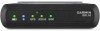
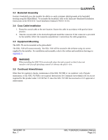
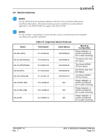
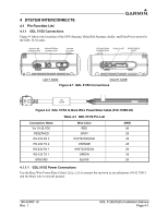
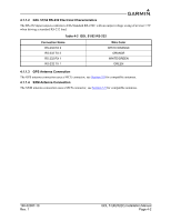
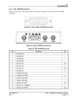
4 SYSTEM INTERCONNECTS 4.1 Pin Function List 4.1.1 GDL 51/52 Connections Figure 4-1shows the locations of the GPS Antenna, SiriusXM Antenna, Audio, and Data/Power ports for the GDL 51/52 units. MICRO-USB CONNECTION SXM ANTENNA CONNECTION POWER BUTTON GPS ANTENNA CONNECTION AUDIO PORT DATA/POWER PORT LEFT SIDE RIGHT SIDE Figure 4-1 GDL 51/52 Connections EMI FILTER Figure 4-2 GDL 51/52 to Bare Wire Power/Data Cable (010-11686-40) Table 4-1 GDL 51/52 Pin List Connection Name Vin 10-32 VDC RESERVED RS-232 RX 2 RS-232 TX 2 RS-232 RX 1 RS-232 TX 1 GROUND Wire Color RED GRAY WHITE/ORANGE ORANGE WHITE/GREEN GREEN BLACK AWG 26 28 28 28 28 28 26 4.1.1.1 GDL 51/52 Power Connections Use the Bare Wire Power/Data Cable (Table 4-2) to connect the red wire to aircraft power (10-32 VDC) and the black wire to aircraft ground. 190-02087-10 Rev. 1 GDL 51(R)/52(R) Installation Manual Page 4-1
-
 1
1 -
2
-
3
-
4
-
5
-
6
-
7
-
8
-
9
-
10
-
11
-
12
-
13
-
14
-
15
-
16
-
17
-
18
-
19
-
20
-
 21
21 -
 22
22 -
 23
23 -
 24
24 -
 25
25 -
 26
26 -
 27
27 -
 28
28 -
 29
29 -
 30
30 -
 31
31 -
32
-
33
-
34
-
35
-
36
-
37
 |
 |