Garmin GDL 52 Installation Manual - Page 29
GDL 51R/52R RS-232 Electrical Characteristics, GDL 51R/52R Aircraft Power
 |
View all Garmin GDL 52 manuals
Add to My Manuals
Save this manual to your list of manuals |
Page 29 highlights
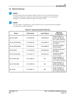
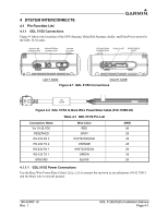
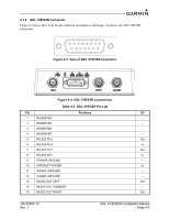
4.1.2.1 GDL 51R/52R Aircraft Power Connect pin 10 to aircraft power (14/28 VDC) and pin 9 to aircraft ground (see Appendix B). It is recommended that a 3 Amp fuse or circuit breaker be used to supply power to the GDL 5XR. 4.1.2.2 GDL 51R/52R RS-232 Electrical Characteristics The RS-232 outputs conform to EIA Standard RS-232C with an output voltage swing of at least ± 5V when driving a standard RS-232 load (see Appendix B). 4.1.2.3 Music Output The MUSIC OUT signals are part of a differential pair (along with the MUSIC RIGHT and MUSIC LEFT signals). The MUSIC OUT COMMON signal should be used as part of a differential pair. See Figure B-2 for an example connection to the GMA245 audio panel. 4.1.2.4 GPS Antenna Connection The GPS antenna connection uses a BNC connector, see Section 3.9 for compatible antennas. 4.1.2.5 SXM Antenna Connection The SXM antenna connection uses a TNC connector, see Section 3.9 for compatible antennas. 4.1.2.6 ADS-B Antenna Connection The GDL 52R ADS-B antenna connection uses a BNC connector, see Section 3.7.1 for compatible antennas. 190-02087-10 Rev. 1 GDL 51(R)/52(R) Installation Manual Page 4-4
-
 1
1 -
2
-
3
-
4
-
5
-
6
-
7
-
8
-
9
-
10
-
11
-
12
-
13
-
14
-
15
-
16
-
17
-
18
-
19
-
20
-
21
-
22
-
23
-
 24
24 -
 25
25 -
 26
26 -
 27
27 -
 28
28 -
 29
29 -
 30
30 -
 31
31 -
 32
32 -
 33
33 -
 34
34 -
35
-
36
-
37
 |
 |
