Garmin GSD 20 Installation Guide
Garmin GSD 20 - GPS Receiver Remote Sonar Sensor Manual
 |
View all Garmin GSD 20 manuals
Add to My Manuals
Save this manual to your list of manuals |
Garmin GSD 20 manual content summary:
- Garmin GSD 20 | Installation Guide - Page 1
GSD 20 Sounder Module installation instructions - Garmin GSD 20 | Installation Guide - Page 2
copy of the sales receipt from the original retailer is required. Garmin will not replace missing components from any package purchased through an online auction. To obtain warranty service, contact your local Garmin authorized dealer or call Garmin Product Support for shipping instructions and an - Garmin GSD 20 | Installation Guide - Page 3
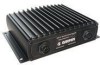
are missing, please contact your Garmin dealer immediately. Included Equipment: • GSD 20 Sounder Module • 30' (9.1 m) Power/Data Cable • Installation Guide for the GSD 20 Optional Transducers The transducer acts as the eyes and ears of your new sonar. The transducer transmits sound waves toward the - Garmin GSD 20 | Installation Guide - Page 4
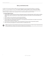
20 module has been installed, connect the power/data and transducer cables to the appropriate receptacle. 6. Refer to the following wiring diagrams for connecting the GSD 20 to compatible Garmin units. NOTE: You can extend the wiring of the GSD 20 power/data cable up to 100' (30 m) total length. Use - Garmin GSD 20 | Installation Guide - Page 5
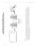
GARMIN GSD 20 SOUNDER MODULE TO TRANSDUCER BATTERY 10-35 VOLTS DC Notes: 1. Power and ground wires require 18 AWG. All other wires require 22 AWG. Use 4-conductor, shielded wiring for runs over 30' (9.1 m). 2. Refer to the GPSMAP 2006/2006C/2010/2010C/3005C/3006C/3010C Installation Instructions - Garmin GSD 20 | Installation Guide - Page 6
INSTALLATION INSTRUCTIONS 4 GSD 20 Sonar Module BASIC WIRING FOR THE GARMIN GSD 20 TO A DUAL GPSMAP 2006/2006C/2010/2010C *This diagram does not apply to the GPSMAP 3005C/3006C/3010C. Refer to Note 4 on the Single GPSMAP 2006/2006C/2010/2010C/3005/C3006C/3010C diagram. ��� - Garmin GSD 20 | Installation Guide - Page 7
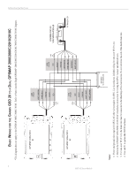
/376C/396 INSTALLATION INSTRUCTIONS ON OFF FUSE 1.5A WIRE COLOR RED BLACK BLUE YELLOW SEE NOTE 3 ON OPTION 1 OFF WIRE COLOR RED FUSE 2A BLACK WHITE/BLUE WHITE/BROWN ORANGE BATTERY 10-35 VOLTS DC SEE NOTE 3 OPTION 2 GARMIN GSD 20 SOUNDER MODULE TO TRANSDUCER Notes: 1. Power and ground - Garmin GSD 20 | Installation Guide - Page 8
/BLUE WHITE/BROWN ORANGE BATTERY 10-35 VOLTS DC SEE NOTE 3 OPTION 2 GARMIN GSD 20 SOUNDER MODULE TO TRANSDUCER Notes: 1. Power and ground wires require 18 AWG. All other wires require 22 AWG. Use 4-conductor, shielded wiring for runs over 30' (9.1 m). 2. For runs over 30' (9.1 m), the drain - Garmin GSD 20 | Installation Guide - Page 9
WHITE/BROWN ORANGE GARMIN GSD 20 SOUNDER MODULE TO TRANSDUCER BATTERY 10-35 VOLTS DC Notes: 1. Power and ground wires require 18 AWG. All other wires require 22 AWG. Use 4-conductor, shielded wiring for runs over 30' (9.1 m). 2. Refer to the GPSMAP 172/172C Owner's Manual for wiring the GPS 17 - Garmin GSD 20 | Installation Guide - Page 10
INSTALLATION INSTRUCTIONS Blink Codes Once the unit is installed, it switches on when the display unit is powered on (or the GSD remote power line is pulled low, with power applied). The two-color (Green/Red) LED on the GSD 20 indicates the current operational status of the module. Codes are: Code - Garmin GSD 20 | Installation Guide - Page 11
Sonar Sounder Power: 500 watts (RMS) 4000 watts (peak to peak) Frequency: 50/200 kHz Depth: 1500 foot max depth* * Depth capacity is dependent on water salinity, bottom type, and other water conditions. Data Output Source: Proprietary Garmin data format. INSTALLATION INSTRUCTIONS GSD 20 - Garmin GSD 20 | Installation Guide - Page 12
© Copyright 2004, 2005 Garmin Ltd. or its subsidiaries Garmin International, Inc. 1200 East 151st Street, Olathe, Kansas 66062, U.S.A. Garmin (Europe) Ltd. Unit 5, The Quadrangle, Abbey Park Industrial Estate, Romsey, SO51 9DL, U.K. Garmin Corporation No. 68, Jangshu 2nd Road, Shijr, Taipei County,
-
 1
1 -
 2
2 -
 3
3 -
 4
4 -
 5
5 -
 6
6 -
 7
7 -
8
-
9
-
10
-
11
-
12
 |
 |
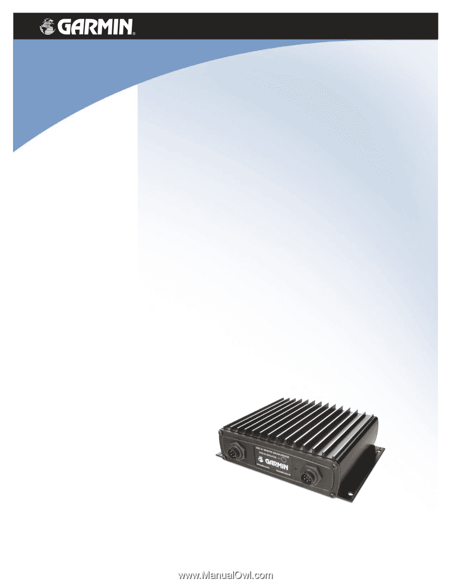
GSD 20
Sounder
Module
installation instructions