Garmin GSD 20 Installation Guide - Page 5
Iring, Armin, Ingle - sonar
 |
View all Garmin GSD 20 manuals
Add to My Manuals
Save this manual to your list of manuals |
Page 5 highlights
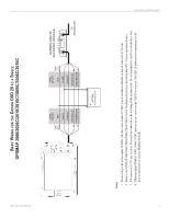
GSD 20 Sonar Module BASIC WIRING FOR THE GARMIN GSD 20 TO A SINGLE GPSMAP 2006/2006C/2010/2010C/3005C/3006C/3010C FUSE 5 A WIRE COLOR RED BLACK ORANGE WHITE/BLUE WHITE/BROWN WIRE COLOR RED FUSE 2 A BLACK ORANGE WHITE/BLUE WHITE/BROWN GARMIN GSD 20 SOUNDER MODULE TO TRANSDUCER BATTERY 10-35 VOLTS DC Notes: 1. Power and ground wires require 18 AWG. All other wires require 22 AWG. Use 4-conductor, shielded wiring for runs over 30' (9.1 m). 2. Refer to the GPSMAP 2006/2006C/2010/2010C/3005C/3006C/3010C Installation Instructions for wiring the GPS 17 sensor and other devices. 3. For runs over 30' (9.1 m), the drain wire must be connected to the shielding of the extension run. Do not terminate the end of the shield drain wire. 4. When multiple GPSMAP 3005C/3006C/3010C units are in use, only wire the GSD 20 to one unit. The GSD 20 information is transmitted to all units connected to the Garmin Marnine Network. INSTALLATION INSTRUCTIONS 3
-
 1
1 -
 2
2 -
 3
3 -
 4
4 -
 5
5 -
 6
6 -
 7
7 -
 8
8 -
 9
9 -
 10
10 -
 11
11 -
12
 |
 |
