Garmin GSD 21 Installation Instructions - Page 4
Installation Instructions - problems
 |
UPC - 753759052232
View all Garmin GSD 21 manuals
Add to My Manuals
Save this manual to your list of manuals |
Page 4 highlights
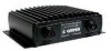
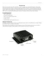
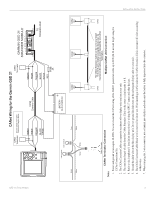
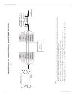
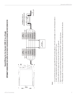
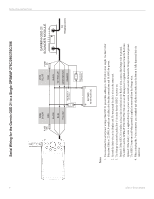
INSTALLATION INSTRUCTIONS INSTALLATION INSTRUCTIONS The GSD 21 must be properly installed according to the following CANet or Serial installation instructions to get the best possible performance. To complete the installation, you need appropriate fasteners. If you experience difficulty with the installation, contact Garmin Product Support. CANet is a high-speed sonar network. If you are connecting a CANet compatible unit, follow the CANet installation instructions. Using the CANet installation optimizes the performance of the CANet-compatible units. CANet compatible unit devices features, such as UltrascrollTM, are affected if a serial installation is used. The module should be mounted in an out-of-the-way location that is dry and well ventilated. Avoid mounting the module where it can be submerged in liquids or exposed to extreme temperatures. Be sure to mount the module so that the LED is visible. NOTE: When using the chartplotter and GSD 21 on battery power only (engines off) for extended periods of time, be sure there is enough available amperage to run the units for the time period. Running other onboard devices at the same time can lower the available amperage, causing the chartplotter and/or GSD 21 to shut off. Check with your local marine dealer/installer if problems persist. To install the GSD 21 sounder module: 1. After the location is chosen, place the unit. Be sure to allow enough clearance for attaching the cables. Using the module as a template, mark the location of the four mounting holes. If needed, additional mounting holes can be drilled in the side mounting flanges of the module. 2. Attach the GSD 21 to the mounting location using appropriate fasteners. 3. Mount the transducer according to the instructions provided with the transducer. 4. Route the cables according to the CANet or Serial instructions to the mounting locations of the display unit. Use the appropriate tie-wraps, fasteners, and sealant to secure the cable along the route and through any bulkhead or deck. 5. After installing the GSD 21 module, connect the power/data and transducer cables to the appropriate receptacle. 6. Refer to the following CANet and serial wiring diagrams for connecting the GSD 21 to compatible Garmin units. NOTE: You can extend the CANet wiring of the GSD 21 power/data cable up to 80 ft (24.38 m) total length using the CANet Connections Kit. NOTE: You can extend the serial/power wiring of the GSD 21 power/data cable up to 100 ft (30 m) total length. Use the CANet Extension Cable or 22 AWG, 4-conductor shielded cable for data connections and 18 AWG for power. Transducer cable extensions are available through your Garmin dealer. WARNING: Do not connect or disconnect the transducer while the MFD and GSD 21 are connected and turned on . Doing so might damage the GSD 21. 2 GSD 21 Sonar Module
-
 1
1 -
 2
2 -
 3
3 -
 4
4 -
 5
5 -
 6
6 -
 7
7 -
 8
8 -
 9
9 -
 10
10 -
11
-
12
-
13
-
14
 |
 |
