Garmin GSD 21 Installation Instructions - Page 5
CANet Wiring for the Garmin GSD 21 - transducer
 |
UPC - 753759052232
View all Garmin GSD 21 manuals
Add to My Manuals
Save this manual to your list of manuals |
Page 5 highlights
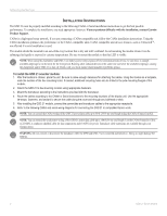
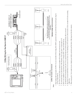
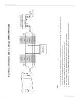
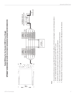
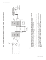
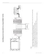
GSD 21 Sonar Module To Sounder Green White CANet Wiring for the Garmin GSD 21 CANet Terminator See the CANet Terminator Connection Diagram Below CANet Terminator GREEN WHITE ORANGE BLACK DRAIN 3 wire connector 3 wire connector CANet Extension Cable BATTERY 10-35 VOLTS DC GREEN WHITE ORANGE BLACK BLACK RED FUSE 2A GARMIN GSD 21 SOUNDER MODULE � TO TRANSDUCER Green White Green White To Chartplotter CANet Unit CANet Unit CANet Unit Notes: CANet Terminator CANet Terminator Connection The CANet Extension Cable can be cut to any length CANet 1 ft to 80 ft and a CANet compatible device can be inserted on the cable at any point between the two CANet Terminators. CANet Multiple CANet Unit Connection 1. Power and ground wires require 18 AWG. You can extend the CANet wiring of the GSD 21 power/data cable up to 80 ft (24.38 m) total length using the CANet Connections Kit. 2. The CANet Extension Cable can support a maximum of two display units and one sonar unit. 3. The maximum length of cable from the CANet Extension Cable to the sonar or display units is 6 ft. 4. Refer to the chartplotter's installation instructions for wiring the GPS 17 sensor and other devices. 5. Ground the drain wire at the first display unit. Do not ground the drain wire on the subsequent display units or sonar unit. 6. The CANet Extension Cable Black wire is reserved for future use. When inserting a CANet unit on the CANet Extension Cable, reconnect all wires according to their color. 7. When crimping the 3-wire connector, use a standard pair of pliers and make sure the button is fully depressed into the connector. INSTALLATION INSTRUCTIONS 3
-
 1
1 -
 2
2 -
 3
3 -
 4
4 -
 5
5 -
 6
6 -
 7
7 -
 8
8 -
 9
9 -
 10
10 -
 11
11 -
12
-
13
-
14
 |
 |
