Garmin GSD 24 Installation Instructions - Page 2
Connecting the Sounder, Connecting the GSD 26 to a Transducer or Sensor, Cable Routing Grommets,
 |
View all Garmin GSD 24 manuals
Add to My Manuals
Save this manual to your list of manuals |
Page 2 highlights
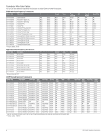
Connecting the Sounder notice Do not force a cable into its port. Forcing the cable can damage the pins. If the cable is properly aligned, the cable should connect easily. If you are connecting 6-pin transducer to a GSD 24 you must use the included adaptor. Refer to the GSD 24 Transducer Adaptor Installation Instructions included in the package for more information. Before you connect the sounder to the network, power, and the transducer, you must mount the sounder (page 1). 1 Route the cables using appropriate tie wraps, fasteners, and sealant to secure the cables along the route and through any bulkhead or deck (page 2). 2 Install the locking rings on the marine network and power cables (page 2). 3 Connect the bare-wire end of the power cable to a 12 Vdc power source and to ground. 4 Align the notch on the end of the power cable with the power port on the device, and press the cable into place. 5 After the cable is seated, turn the locking ring clockwise until it stops. 6 Select an option: • If you are installing a GSD 24, repeat steps 4 and 5 for the network and transducer cables. • If you are installing a GSD 26, repeat steps 4 and 5 for the network cable, and refer to "Connecting the GSD 26 to a Transducer" on page 2. 7 Select an option: • If your boat is equipped with a GMS™ 10 network port expander, connect the network cable to an available port on the GMS 10. • If your boat is not equipped with a GMS 10 network port expander, connect the network cable directly to the NETWORK port on your chartplotter. Connecting the Wires Before you connect the wires, consult the wiring diagrams on pages 3-4 to view the proper wiring configuration for your transducer and the wiring tables on page 4 to view specific examples of many Garmin/Airmar transducer wire colors. 1 Connect the uninsulated section of each wire to the terminal block using a 3 mm flat screwdriver. 2 Connect the bare shield wire to one of the two ground posts under the terminal block using a #2 Phillips screwdriver. Finalizing the Connection 1 After all the wire connections are secure, use a 1 in. (24 mm) wrench to tighten the nut around the transducer cable. When tightening correctly you will not be able to pull the transducer cable out of the housing. 2 Install cord grip plugs in the unused cord grips. 3 Replace and secure the terminal block lid on the sounder with a #2 Phillips screwdriver. The sounder will not operate with the lid removed. Grounding the Sounder Before you ground the sounder, you must mount it (page 1) and connect the marine network, power, transducer, and sensors (page 2). The chassis ground post is located on the exterior of the chassis, adjacent to a corner mounting hole. Connect the chassis ground post ➊ to the boat water ground circuit. ➊ Connecting the GSD 26 to a Transducer or Sensor NOTICE You must install cord grip plugs in any unused cord grip to ensure that water cannot enter the transducer wiring block area and damage the sounder. The terminal blocks are not removable. Preparing the Cable 1 Remove the terminal block lid from the sounder with a #2 Phillips screwdriver. 2 Select an option: • Feed a sensor cable through the small cord grip ➊, and pull it into the terminal block area. • Feed a transducer cable through one of the large cord grips ➋ on the housing, and pull it into the terminal block area. Do not tighten the cord grips at this time. Cable Routing Grommets notice Cable routing grommets do not create a waterproof seal. To create a waterproof seal, apply a marine sealant around the grommet and cable after installation. Be sure to test the system before sealing the grommets. When routing cables through your boat, it may be necessary to drill holes to route the connector end of the cables. Rubber grommets are provided to cover the cable holes for a finished look. You can purchase additional grommets from your Garmin dealer or directly from Garmin at www.garmin.com. Installing the Cable Grommet 1 Mark the location where you want to route the cable. 2 Using a 1 1/4 in. (32 mm) paddle drill bit or hole saw, drill the installation hole. 3 Route the cable through the hole to the sounder. 4 Spread the grommet apart at the split, and place it around the cable. 5 Firmly push the grommet into the installation hole until it is seated. 6 Apply marine sealant, as needed, to weatherproof the installation hole (optional). ➊ ➋ Installing Locking Rings on the Cables Before you install locking rings on the cables, you must route the cables. To help make the cable-routing process easier, the locking rings are packaged separately from the cables. Each locking ring is packaged in a small bag with a number on the label for easy identification. 1 Separate the two halves of the locking ring ➊. 2 GSD 24/26 Installation Instructions
-
 1
1 -
 2
2 -
 3
3 -
 4
4 -
 5
5 -
 6
6
 |
 |