Garmin GT41-TH - Stainless Steel Thru-Hull DownVü/SideVü 500 W CHIRP 2 - Page 2
Cored Fiberglass Boat Hull Installation, Instructions
Page 2 highlights
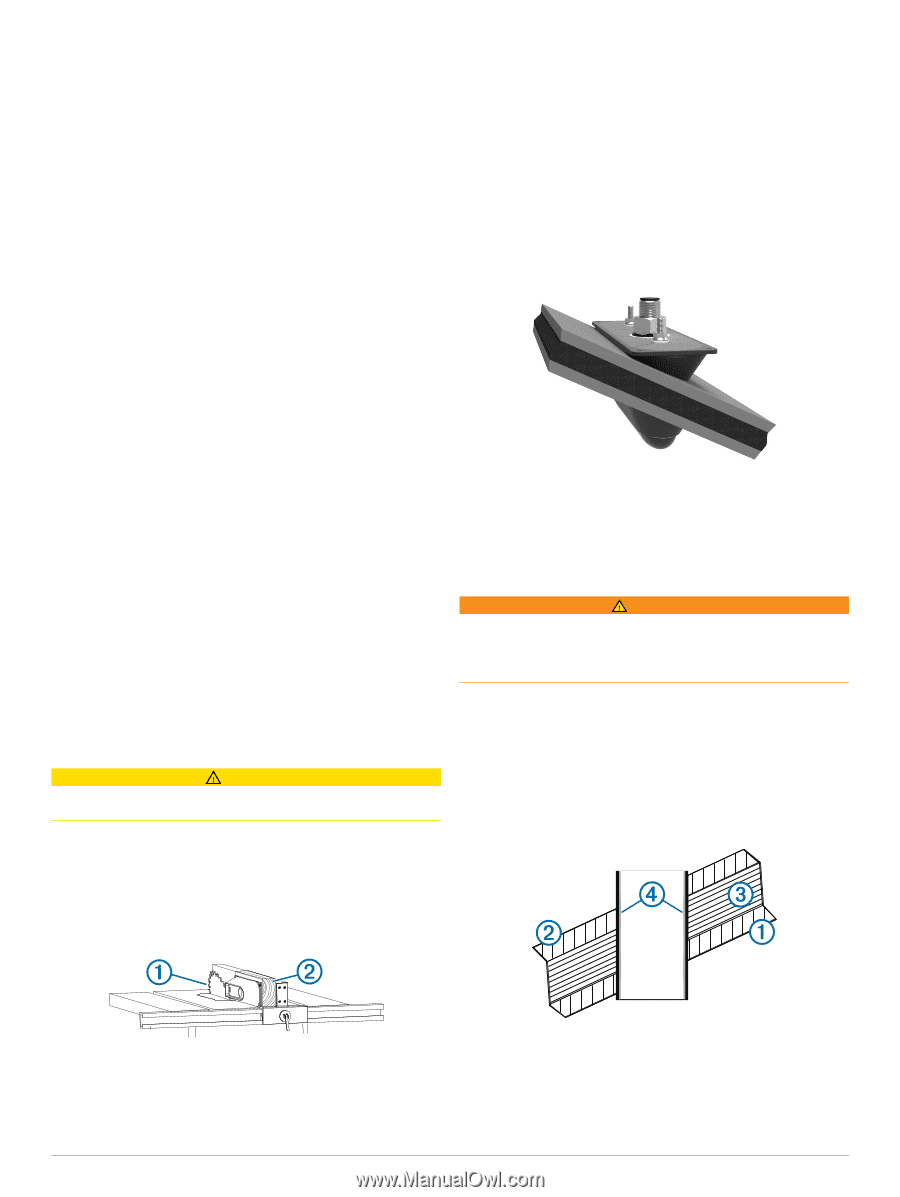
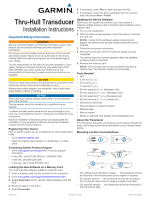
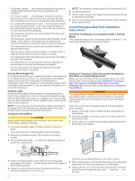
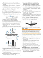
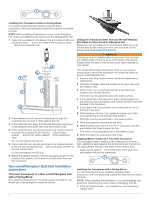
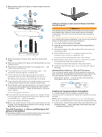
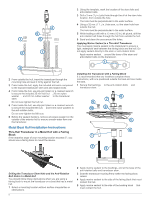
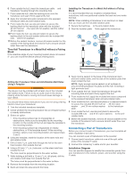
• On full-keel vessels , the transducer should be mounted at à a slight angle that aims at the bow, not parallel to the centerline. • On fin-keel vessels , the transducer should be mounted Ä from 25 cm to 75 cm (from 10 to 30 in.) in front of the keel and a maximum of 10 cm (4 in.) to the side of the centerline. • On vessels with displacement hulls , the transducer should be mounted approximately 1/3 aft of Å the waterline length of the vessel from the bow, and from 150 to 300 mm (from 6 to 12 in.) to the side of the centerline. • The transducer should be mounted parallel to the bow-stern axis of your vessel. • The transducer should not be mounted behind strakes, struts, fittings, water intake or discharge ports, or anything that creates air bubbles or causes the water to become turbulent. The transducer must be in clean (non-turbulent) water for optimal performance. • The transducer should not be mounted in a location where it might be jarred when launching, hauling, or storing. • On single-drive boats, the transducer must not be mounted in the path of the propeller. The transducer can cause cavitation that can degrade the performance of the boat and damage the propeller. • On twin-drive boats, the transducer should be mounted between the drives, if possible. Fairing Block Angle Cut A fairing block positions your transducer parallel to the water line for increased sonar accuracy. You must measure the deadrise angle of your boat hull to determine if a fairing block is necessary to mount the transducer. If the deadrise angle of your mounting location exceeds 5°, you should use a fairing block to mount the transducer. Deadrise Angle Deadrise is the angle formed between a horizontal line and a boat hull at a single point. You can measure the deadrise angle with an angle finder, a protractor, or a digital level. You can also ask your boat manufacturer for the deadrise angle of the specific point on your boat hull. NOTE: A boat may have several deadrise angles depending on the shape of the hull. Measure the deadrise angle only at the location where you plan to install the transducer. Cutting the Fairing Block CAUTION Always wear safety goggles, ear protection, and a dust mask when drilling, cutting, or sanding. 1 Using wood screws, attach the fairing block to a piece of wood. The wood becomes a cutting guide for the fairing block. 2 Measure the deadrise angle of the hull at the mounting location. 3 Tilt your table saw blade to match the deadrise angle and À secure the cutting fence. NOTE: The maximum cutting angle of the fairing block is 25°. 6 Cut the fairing block. 7 Using a rasp or power tool, shape the fairing block to the hull as precisely as possible. 8 Use the remaining section of the fairing block as the backing block inside the hull. Cored Fiberglass Boat Hull Installation Instructions Thru-Hull Transducer in a Cored Hull with a Fairing Block If the deadrise angle of your mounting location exceeds 5°, you must use a fairing block to mount the device. Drilling the Transducer Stem Hole and the Anti-Rotation Bolt Holes in a Cored Fiberglass Hull Before you can drill holes for the anti-rotation bolts, you must drill the hole for the transducer stem (Drilling the Transducer Stem Hole and the Anti-Rotation Bolt Holes in a Cored Fiberglass Hull) and you must cut the fairing block (Cutting the Fairing Block). WARNING The device must be installed with at least one of the included anti-rotation bolts. Failure to do so could result in the device rotating while the boat is moving and could cause damage to your vessel. The core must be cut and sealed carefully to protect against water seepage. 1 Select a mounting location without surface irregularities or obstructions. 2 Using the template, mark the location of the stem hole and anti-rotation bolts. 3 Drill a 3 mm (1/8 in.) pilot hole through the template and hull at the stem hole location. 4 Position the fairing block on the table so the cutting guide rests against the fence and the angle matches the angle of Á the mounting location . 5 Adjust the cutting fence to ensure the fairing block has a minimum thickness of 13 mm (1/2 in.). 2 The hole must be perpendicular to the water surface. 4 Place masking tape over the pilot hole and surrounding area outside the hull to prevent damage to the fiberglass. 5 Using a 25 mm (1 in.) bit at the stem hole location, drill from outside the hull through the outer skin , inner skin , and the core . À Á Â
-
 1
1 -
 2
2 -
 3
3 -
 4
4 -
 5
5 -
 6
6 -
 7
7 -
 8
8
 |
 |