Garmin GT41-TH - Stainless Steel Thru-Hull DownVü/SideVü 500 W CHIRP 2 - Page 7
Connecting a Pair of Transducers
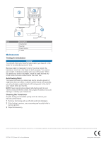
Page 7 highlights
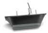
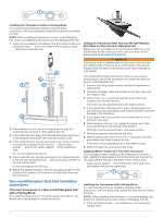
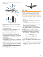
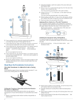
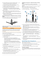
6 From outside the hull, insert the transducer cable and Å transducer housing through the mounting hole. 7 From inside the hull, slide the backing block onto the transducer and seat it firmly against the hull. 8 Apply the included anti-seize compound to the exposed transducer stem and anti-rotation bolts. 9 From inside the hull, use slip-joint pliers to secure the backing block to the transducer stem with the included 35 mm hull nut , the nylon 26 mm washer, and the rubber Æ 24 mm washer . Ç 10From inside the hull, use slip-joint pliers to secure the backing block to the anti-rotation bolts with the included M8 nuts and 8 mm washers . È É 11Before the sealant hardens, remove all excess sealant on the outside of the fairing block and exterior hull to ensure smooth water flow over the transducer. Thru-Hull Transducer in a Metal Hull without a Fairing Block If the deadrise angle of your mounting location does not exceed 5°, you can mount the device without a fairing block. Installing the Transducer in a Metal Hull without a Fairing Block It is recommended that two installers complete these instructions, with one positioned outside the boat and one inside the boat. NOTE: When installing a transducer in an aluminum or steel hull, you must use the included isolation plate. 1 Secure the bushings to the anti-rotation bolts . À Á 2 Seat the isolation plate firmly against the transducer.  Drilling the Transducer Stem and Anti-Rotation Bolt Holes Using a Template WARNING The device must be installed with at least one of the included anti-rotation bolts. Failure to do so could result in the device rotating while the boat is moving and could cause damage to your vessel. You should follow these instructions if you are not using a fairing block to mount your transducer. 1 Trim the included transducer template. 2 Check whether the mounting location has an irregular surface or nearby obstructions. 3 Select an option: • If the mounting surface has no irregularities or obstructions, make sure the template fits the mounting location on the outside of the hull and tape the template to the mounting location. • If the mounting surface has irregularities or nearby obstructions, or if the template doesn't fit the mounting location, select a new mounting location and repeat steps 2 and 3. 4 Using the template, mark the location of the stem hole and anti-rotation bolts. 5 Drill a 3 mm (1/8 in.) pilot hole through the hull at the stem hole location, from outside the hull. 6 Using a 32 mm (1 1/4 in.) hole saw, cut the stem hole from outside the hull. The hole must be perpendicular to the water surface. 7 While holding a drill with a 12 mm (1/2 in.) bit plumb, drill the anti-rotation bolt holes from outside the hull. The holes must be perpendicular to the water surface. 8 Remove the template from the mounting location. 9 Sand and clean the area around the holes. 3 Apply marine sealant to the base of the transducer stem à and anti-rotation bolts, and the side of the isolation plate that must contact the hull. NOTE: Apply enough marine sealant on all surfaces to ensure bonding between the plate and the hull, including a tight perimeter seal. 4 From outside the hull, insert the transducer through the mounting hole and seat it firmly against the hull. 5 From inside the hull, apply the included anti-seize compound to the exposed transducer stem and anti-rotation bolts. 6 From inside the hull, use slip-joint pliers or a crescent wrench to secure the included 35 mm hull nut , 26 mm nylon Ä washer , and 24 mm rubber washer to the transducer Å Æ stem. 7 From inside the hull, use slip-joint pliers to secure the included M8 nuts and 8 mm nylon washers to the anti- Ç È rotation bolts. 8 Before the sealant hardens, remove all excess sealant on the outside of the exterior hull to ensure smooth water flow over the transducer. Connecting a Pair of Transducers Before you connect a pair of transducers, you must complete all other installation instructions. You can connect a pair of transducers to the sounder. 1 Connect each transducer cable into one of the split cable ends of the included Y-cable. 2 Connect the remaining Y-cable end to your sounder. Installation Diagram You can use this diagram to identify the connection points from your transducers to the network, power, and sounder using the Y-cable. 7
-
 1
1 -
 2
2 -
 3
3 -
 4
4 -
 5
5 -
 6
6 -
 7
7 -
 8
8
 |
 |