Garmin GTX 23 ES Installation Manual - Page 17
Installation Overview
 |
View all Garmin GTX 23 ES manuals
Add to My Manuals
Save this manual to your list of manuals |
Page 17 highlights
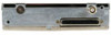
2 INSTALLATION OVERVIEW 2.1 Introduction This section provides hardware equipment information for installing the GTX 23 Mode S transponder, related hardware, and optional accessories. Installation of the GTX 23 should follow the data detailed in this manual. Cabling is fabricated by the installing agency to fit each particular aircraft. The guidance of FAA advisory circulars AC 43.13-1B and AC 43.13-2B, where applicable, may be found useful for making retro-fit installations that comply with FAA regulations. Refer to Appendix D for rack drawings and dimensions. 2.2 Installation Materials The GTX 23 is available as a single unit under the following part numbers: Item Catalog Part Number GTX 23 w/ES, Unit Only, (011-02803-02) 010-01014-02 GTX 23 w/ES and Install Kit, (011-02803-02) 010-01014-03 2.2.1 Equipment Available Each of the following accessories is provided separately for the GTX 23 unit. The rack and the remainder of the accessories are required for installation. Item Garmin Catalog Part Number GTX 23 Stand-Alone Install Rack 115-00629-00 Connector Kit, GTX 23 011-01012-01 Back-plate Assembly, GTX 23 011-00582-00 Garmin Transponder Antenna kit* 010-10160-00 *Note: A transponder antenna approved to TSO C66( ) or C74( ) that has been installed to meet the requirements of this manual may be used with the GTX 23. 2.2.2 Additional Equipment Required The following installation accessories are required but not provided: • Cables - The installer will supply all system cables including circuit breakers. Cable requirements and fabrication is detailed in Section 3 of this manual. • Hardware - #6-32 x 100° Flathead SS Screw [(MS24693, AN507R or other approved fastener) (4 ea.)] for horizontal mounting of the remote stand-alone rack. • Hardware - #8-32 Panhead Machine Screw [(MS35206, AN526 or other approved fastener) (4 ea.)] for vertical mounting of the remote stand-alone rack. 2.3 Installation Considerations 2.3.1 Preservation of Previous Systems It is the installer's responsibility to preserve the essential characteristic of the aircraft being modified with this equipment to be in accordance with the aircraft manufacturer's original design. This includes the preservation of multiple power buses, which reduces the probability of interrupting power to essential instruments and avionics. GTX 23 Installation Manual 190-00906-01 Page 2-1 Revision A
-
 1
1 -
2
-
3
-
4
-
5
-
6
-
7
-
8
-
9
-
10
-
11
-
 12
12 -
 13
13 -
 14
14 -
 15
15 -
 16
16 -
 17
17 -
 18
18 -
 19
19 -
 20
20 -
 21
21 -
 22
22 -
23
-
24
-
25
-
26
-
27
-
28
-
29
-
30
-
31
-
32
-
33
-
34
-
35
-
36
-
37
-
38
-
39
-
40
-
41
-
42
-
43
-
44
-
45
-
46
-
47
-
48
-
49
-
50
-
51
-
52
 |
 |
