Garmin GTX 23 ES Installation Manual - Page 23
INSTALLATION PROCEDURE, Unpacking Unit, Wiring Harness Installation, Electrical Connections
 |
View all Garmin GTX 23 ES manuals
Add to My Manuals
Save this manual to your list of manuals |
Page 23 highlights
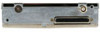
3 INSTALLATION PROCEDURE 3.1 Unpacking Unit Carefully unpack the equipment and make a visual inspection of the unit for evidence of damage incurred during shipment. If the unit is damaged, notify the carrier and file a claim. To justify a claim, save the original shipping container and all packing materials. Do not return the unit to Garmin until the carrier has authorized the claim. Retain the original shipping containers for storage. If the original containers are not available, a separate cardboard container should be prepared that is large enough to accommodate sufficient packing material to prevent movement. 3.2 Wiring Harness Installation Allow adequate space for installation of cables and connectors. The installer shall supply and fabricate all cables. All electrical connections to the GTX 23 are made through one 62-pin D-subminiature connector. Section 4 defines the electrical characteristics of all input and output signals. Required connectors and associated hardware are supplied with the connector kit. See Appendix C for examples of interconnect wiring diagrams. CAUTION Check wiring connections for errors before inserting the GTX 23 into the rack. Incorrect wiring could cause internal component damage. 3.3 Electrical Connections All electrical connections, except for the antenna and shield ground, are made through a single 62 pin D-subminiature connector (see Figure 4-1). Table 4-1 lists the electrical connections of all input and output signals. See Appendix C for interconnect wiring diagrams and cable requirements for each signal. Required connector and associated hardware are supplied in the connector kit (P/N 011-01012-01). . CAUTION Check wiring connections for errors before inserting the GTX 23 into the rack. Incorrect wiring could cause internal component damage. Table 3-1: Pin Contact Part Numbers Manufacturer Garmin P/N Military P/N AMP Positronic ITT Cannon 62 pin D-Subminiature connector (P2301) 18 AWG (Power Only) 20-24 AWG 336-0004400 336-00021-00 N/A M39029/58-360 N/A 204370-2 N/A MC8522D N/A 030-2042-000 GTX 23 Installation Manual 190-00906-01 Page 3-1 Revision A
-
 1
1 -
2
-
3
-
4
-
5
-
6
-
7
-
8
-
9
-
10
-
11
-
12
-
13
-
14
-
15
-
16
-
17
-
 18
18 -
 19
19 -
 20
20 -
 21
21 -
 22
22 -
 23
23 -
 24
24 -
 25
25 -
 26
26 -
 27
27 -
 28
28 -
29
-
30
-
31
-
32
-
33
-
34
-
35
-
36
-
37
-
38
-
39
-
40
-
41
-
42
-
43
-
44
-
45
-
46
-
47
-
48
-
49
-
50
-
51
-
52
 |
 |
