Garmin GTX 33 Installation Manual
Garmin GTX 33 Manual
 |
View all Garmin GTX 33 manuals
Add to My Manuals
Save this manual to your list of manuals |
Garmin GTX 33 manual content summary:
- Garmin GTX 33 | Installation Manual - Page 1
GTX 33 Transponder Installation Manual 190-00906-00 June, 2012 Revision F - Garmin GTX 33 | Installation Manual - Page 2
Support Line (Toll Free): (888) 606-5482 www.garmin.com Garmin installation drawings and interconnects, added ETSO information Added GTX 33H, GTX 33DH, and non-extended squitter units info, simplified doc title Added ADS-B info Added TNC connectors Page A Revision F GTX 33 Installation Manual - Garmin GTX 33 | Installation Manual - Page 3
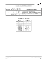
Number(s) 2-2 2-6 C-2 and C-4 Section Number 2.2.1 2.4.1 C Description of Change Added new back-plate assemblies Corrected Cable Routing Considerations Section Added new installation - 3-6 4-1 - 4-10 A-1 - A-2 B-1 - B-16 C-1 - C-6 D-1 - D-7 190-00906-00 Rev. F GTX 33 Installation Manual Page i - Garmin GTX 33 | Installation Manual - Page 4
in whole or in part of this manual. WARNING This product, its garmin.com/prop65. NOTE Throughout this document references made to GTX 33 shall equally apply to the GTX 33, GTX 33D, GTX 33H, and GTX 33DH, with or without Extended Squitter; except where specifically noted. GTX 33 Installation Manual - Garmin GTX 33 | Installation Manual - Page 5
List...4-1 4.2 Power Functions ...4-4 4.3 Temperature Inputs...4-4 4.4 Altitude Functions ...4-5 4.5 Discrete Functions ...4-7 4.6 Serial Data Electrical Characteristics 4-8 4.7 RS-232 Input/Output, Software Update Connections 4-11 190-00906-00 Rev. F GTX 33 Installation Manual Page iii - Garmin GTX 33 | Installation Manual - Page 6
.A-1 A.1 Static Test Loading ...A-1 A.2 Determining Static Load Capability A-1 Appendix B VERSION 1 ADS-B FIELD APPROVAL COMPLIANCE MATRIX ...B-1 Appendix C OUTLINE AND INSTALLATION DRAWINGS C-1 Appendix D INTERCONNECT DRAWINGS D-1 GTX 33 Installation Manual Page iv 190-00906-00 Rev. F - Garmin GTX 33 | Installation Manual - Page 7
GTX 33. Mod Levels are listed with the associated service bulletin number, service bulletin date, and the purpose of the modification. The table is current at the time of publication of this manual (see date on front cover) and is subject to change without notice. Authorized Garmin Sales and Service - Garmin GTX 33 | Installation Manual - Page 8
GTX 33 P/N 011-00779-50, 011-00779-70 HARDWARE MOD LEVEL HISTORY MOD LEVEL None at this time SERVICE BULLETIN NUMBER SERVICE BULLETIN DATE PURPOSE OF MODIFICATION GTX 33 Installation Manual Page vi 190-00906-00 Rev. F - Garmin GTX 33 | Installation Manual - Page 9
GTX 33 Mode S Transponder. These versions include all GTX 33, GTX 33D, GTX 33H, and GTX 33DH units with or without Extended Squitter Enabled; as part of a Garmin Integrated Flight Deck. Throughout this manual, the term GTX 33 applies to all versions of the GTX 33 and GTX 33D unless specifically - Garmin GTX 33 | Installation Manual - Page 10
recognized by regulatory authorities. As show in the table below, the Garmin GTX 33 w/ES currently supports ADS-B Out 1090MHz Extended Squitter capability meeting 'Version 1' ADS-B system requirements. NOTE GTX 33 w/ES transponders with software version 6.20 or earlier are not compliant with - Garmin GTX 33 | Installation Manual - Page 11
location of all transponder equipped aircraft within a specified service volume. The TIS ground sensor uses real time track reports to generate traffic notification. Traffic display is available to aircraft equipped with a Mode S data link such as the Garmin GTX 33 transponder. Traffic can then be - Garmin GTX 33 | Installation Manual - Page 12
and GTX 33D 010-00294-() support the following list of Comm-B Definition Subfield (BDS) registers: • BDS (0,0) Air Initiated Comm-B (AICB). • BDS (1,0) Data Link Capability Report. • BDS (1,7) Common Usage Ground Initiated Comm-B (GICB) Capability Report. • BDS (1,8) Mode S Specific Services GICB - Garmin GTX 33 | Installation Manual - Page 13
Specifications It is the responsibility of the installing agency to obtain the latest revision of the GTX 33 Environmental Qualification Form. This form is available directly from Garmin under the following part number: GTX 330/GTX 33/GTX 328/GTX 23 Environmental Qualification Form, Garmin part - Garmin GTX 33 | Installation Manual - Page 14
33 General Specifications Characteristic Regulatory Compliance; GTX 33 w/ES, GTX 33D w/ES Unit Software Complex Electronic Hardware FCC Authorization Temperature Range Altitude Transmitter Frequency Transmitter Power Receiver Frequency Receiver Sensitivity Mode A Capability Mode C Capability Mode - Garmin GTX 33 | Installation Manual - Page 15
this equipment is guaranteed to meet federal communications commission acceptance over the operating temperature range. Modifications not expressly approved by Garmin could invalidate the license and make it unlawful to operate the equipment. 190-00906-00 Rev. F GTX 33 Installation Manual Page 1-7 - Garmin GTX 33 | Installation Manual - Page 16
the aircraft installation conditions are within the TSO standards. TSO articles must have separate approval for installation in an aircraft. The article may be installed only if performed under 14 CFR part 43 or the applicable airworthiness requirements. GTX 33 Installation Manual Page 1-8 190 - Garmin GTX 33 | Installation Manual - Page 17
GTX 33/GTX 33D TSO/ETSO/RTCA/ICAO Compliance Table 1-5. GTX 33/GTX 33D TSO/ETSO/RTCA/ICAO Compliance Function Air Traffic Control Radar Beacon System/Mode Select (ATCRBS/MODE S) Airborne Equipment Traffic Information Service (TIS) Performance Standard TSO-C112 RTCA DO-239 Air Traffic Part Number - Garmin GTX 33 | Installation Manual - Page 18
33H/GTX 33DH TSO/ETSO/RTCA/ICAO Compliance Table 1-6. GTX 33H/GTX 33DH TSO/ETSO/RTCA/ICAO Compliance Function Air Traffic Control Radar Beacon System/Mode Select (ATCRBS/MODE S) Airborne Equipment Traffic Information Service (TIS) Air Traffic Control Radar Beacon System/Mode Select (ATCRBS/MODE - Garmin GTX 33 | Installation Manual - Page 19
The following publications are sources of additional information for installing the GTX 33. Before installing the unit, the technician should read all relevant referenced materials along with this manual. Table 1-8. GTX 33 Reference Documents Part Number 190-00303-00 190-00303-04 560-1025-07 - Garmin GTX 33 | Installation Manual - Page 20
for service. Garmin International, Inc. Garmin (Europe) Ltd. 1200 E. 151st Street Liberty House Olathe, KS 66062, U.S.A. Bulls Copse Road Phone: 800/800.1020 Hounsdown Business Park FAX: 913/397.0836 Southampton, SO40 9RB, UK Telephone: 44 (0) 8708501241 GTX 33 Installation Manual Page - Garmin GTX 33 | Installation Manual - Page 21
2-1. GTX 33 Part Numbers Item GTX 33, Unit Only, (011-00779-00) GTX 33 and Install Kit, (011-00779-00) GTX 33D, Unit Only (011-00779-01) GTX 33D and Install Kit (011-00779-01) GTX 33, Unit Only (011-00779-10) GTX 33 and Install Kit (011-00779-10) GTX 33 w/ ES, Unit Only, (011-00779-20) GTX 33 w/ ES - Garmin GTX 33 | Installation Manual - Page 22
for installation. Table 2-2. GTX 33 Accessories Item Modular Install Rack, GTX 33/GTX 33D G1000 Nutplate Kit Or GTX 33/GTX 33D Stand-Alone Install Rack (Alternate Configuration) Or GTX 33H/GTX 33DH Stand-Alone Install Rack Garmin Catalog Part Number 115-00438-00 (For use with GTX 33 and GTX 33D - Garmin GTX 33 | Installation Manual - Page 23
for mounting of the remote stand-alone rack for GTX 33H and GTX 33DH. • Encoding Altitude Digitizer - For GNS 480 (CNX80), GTN 6XX/7XX, and GMX 200 (MX20) installation. Use encoding altimeter manufacturer's instructions. The Garmin GAE 43 (Garmin P/N 013-00066-00) can provide altitude data in either - Garmin GTX 33 | Installation Manual - Page 24
ground plane material must be added. Conductive wire mesh, radials, or thin aluminum sheets embedded in the composite material provide the proper ground plane allowing the antenna gain pattern to be maximized for optimum transponder performance. GTX 33 Installation Manual Page 2-4 190-00906-00 Rev - Garmin GTX 33 | Installation Manual - Page 25
/127-RG393 RG-304 RG-393 See current issue of Qualified Products List QPL-17 RG types are obsolete and are shown for reference only; replaced by M17 type numbers. 190-00906-00 Rev. F GTX 33 Installation Manual Page 2-5 - Garmin GTX 33 | Installation Manual - Page 26
engineering support pertaining to the design and approval of such pressurized aircraft antenna installations, it is recommended that the installer proceed . 2.6 Cooling Air Refer to the G1000 System Installation manual, Garmin part number 190-00303-00, for information on cooling requirements. - Garmin GTX 33 | Installation Manual - Page 27
33H and GTX 33DH installations. Figure B-4 gives the stand-alone rack dimensions for the GTX 33H and GTX 33DH. The rack can be mounted in any orientation using screws as defined in Section 2.2.2. Ensure that the GTX 33 chassis has a ground path to the airframe by having at least one mounting screw - Garmin GTX 33 | Installation Manual - Page 28
Figure 2-2. GTX 33 Modular Rack (115-00438-00) Figure 2-3. GTX 33 Stand-Alone Rack (115-00629-00) GTX 33 Installation Manual Page 2-8 190-00906-00 Rev. F - Garmin GTX 33 | Installation Manual - Page 29
Figure 2-4. GTX 33H Stand-Alone Rack (011-02422-00) 190-00906-00 Rev. F GTX 33 Installation Manual Page 2-9 - Garmin GTX 33 | Installation Manual - Page 30
Figure 2-5. GTX 33 Stand-Alone Rack, Suggested Mounting Locations GTX 33 Installation Manual Page 2-10 190-00906-00 Rev. F - Garmin GTX 33 | Installation Manual - Page 31
, save the original shipping container and all packing materials. Do not return the unit to Garmin until the carrier has authorized the claim. Retain the original shipping containers for storage. If the packing material to prevent movement. 190-00906-00 Rev. F GTX 33 Installation Manual Page 3-1 - Garmin GTX 33 | Installation Manual - Page 32
standards. CAUTION Check wiring connections for errors before inserting the GTX 33 into the rack. Incorrect wiring could cause internal component damage. Table 3-1. Pin Contact Part Numbers Manufacturer (Note 1) Garmin P/N Military P/N AMP Positronic ITT Cannon 62 pin D-Subminiature 18-20 - Garmin GTX 33 | Installation Manual - Page 33
provided in the G1000 System Installation Manual (190-00303-00), as well as the SPIDER Installation Instructions (190-00313-03) and Shield Block Installation Instructions (190-00313-09). Non-G1000 Installations: GTX 33 installations mounted as a remote transponder system, the connector and backshell - Garmin GTX 33 | Installation Manual - Page 34
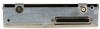
5. Backshell Lid. Provides access when servicing the connector. Figure 3-1. Backshell Connector Assembly (Top: Exploded View. Bottom: Assembled.) GTX 33 Installation Manual Page 3-4 190-00906-00 Rev. F - Garmin GTX 33 | Installation Manual - Page 35
the GTX 33H/33DH in place using the install screw. Tighten the screw until the connectors are fully mated and the retaining wedge in the rack is fully mated with the wedge attached to the unit. Tighten to the torque specification shown in Appendix C. 190-00906-00 Rev. F GTX 33 Installation Manual - Garmin GTX 33 | Installation Manual - Page 36
, refer to the G1000 Line Maintenance and Configuration Manual, Garmin part number 190-00303-04. For actual aircraft installation/checkout, use only aircraft manufacturer approved checkout procedures. Verify proper operation of the transponder by testing in accordance with Appendix F to 14 - Garmin GTX 33 | Installation Manual - Page 37
, (and J3303 for GTX 33D) to an antenna or a 50 Ω, 5-Watt load. The GTX 33 transmits Mode S acquisition squitter replies about once per second whether interrogations are received or not. Verify proper operation of the transponder by testing as specified in Appendix F of 14 CFR, Part 43, to AC 43 - Garmin GTX 33 | Installation Manual - Page 38
3.8 Continued Airworthiness Test according to Title 14 CFR §§ 91.411 and 91.413 as well as Part 43 Appendix F. Other than for regulatory checks, maintenance of the GTX 33 is 'on condition' only. GTX 33 Installation Manual Page 3-8 190-00906-00 Rev. F - Garmin GTX 33 | Installation Manual - Page 39
IN 1 190-00906-00 Rev. F I/O In In In In In In In In In In In In In In Out Out In -Out -In In GTX 33 Installation Manual Page 4-1 - Garmin GTX 33 | Installation Manual - Page 40
B 30 ARINC 429 OUT 2 A 31 EXTERNAL SUPPRESSION I/O 32 ARINC 429 IN 1 A 33 ARINC 429 IN 2 A 34 ARINC 429 OUT 1 B 35 ARINC 429 IN 1 B 36 ) 51 SIGNAL GROUND 52 RESERVED 53 RESERVED 54 XPDR REMOTE POWER OFF GTX 33 Installation Manual Page 4-2 I/O Out In Out In -Out In Out I/O In - Garmin GTX 33 | Installation Manual - Page 41
-- 59 NOT USED -- 60 AIRCRAFT POWER 2 In 61 NOT USED -- 62 SWITCHED POWER OUT Out *Indicates Active Low (Ground to activate) 190-00906-00 Rev. F GTX 33 Installation Manual Page 4-3 - Garmin GTX 33 | Installation Manual - Page 42
input to the GTX 33 transponder. The Temperature input Garmin GTP 59 or an AD590-KH or AD592 made by Analog Devices. The GTX 33 is not configurable for different types of temperature sensors. The temperature-input specification is 1 micro amp per degree Kelvin (1 uA/°K). GTX 33 Installation Manual - Garmin GTX 33 | Installation Manual - Page 43
connecting two GTX 33 transdponders to a Garmin GNS 480 (CNX80), the unit can only receive serial data from one transponder at a time. Use a DPDT switch to connect both serial data and External Standby Select. Refer to Figure D-4. Among the surveillance items the Mode S transponder will transmit - Garmin GTX 33 | Installation Manual - Page 44
GTX 33, it is best to install two digital sources, connecting one encoder to each transponder. 4.4.3 Altimeter Selection Priority When connecting the transponder to a GNS 480 (CNX80) or GTN 6XX/7XX the installer must be aware of the GTX 33 CNX80), GTN 6XX/7XX, or Garmin Integrated Flight Deck (25') - Garmin GTX 33 | Installation Manual - Page 45
the GNS 480 (CNX80) Installation Manual or the appropriate GTN 6XX/7XX Installation Manual for the altitude data reporting GTX 33. External suppression should be connected if another transponder or DME is installed in the aircraft avionics system. Depending on system configuration, the Garmin - Garmin GTX 33 | Installation Manual - Page 46
power cycle. Refer to the GNS 480 (CNX80) Installation Manual or appropriate GTN 6XX/7XX Installation Manual for AUDIO configuration. 4.6 Serial Data Electrical Characteristics The GTX 33 manages support for several equipment interfaces. The GTX 33 can be configured to include GPS, Airdata, AHRS - Garmin GTX 33 | Installation Manual - Page 47
I/O P3301 37 Out P3301 34 Out P3301 32 In P3301 35 In P3301 33 In P3301 36 In P3301 30 Out P3301 28 Out P3301 26 In P3301 ARINC 429 electrical specifications when loaded with up to five standard ARINC 429 receivers. 190-00906-00 Rev. F GTX 33 Installation Manual Page 4-9 - Garmin GTX 33 | Installation Manual - Page 48
ms 100 ms 100 ms 100 ms 100 ms 100 ms 100 ms 500 ms 500 ms 100 ms 100 ms 500 ms 500 ms GTX 33 Installation Manual Page 4-10 190-00906-00 Rev. F - Garmin GTX 33 | Installation Manual - Page 49
in the aircraft, transponder removal and reinstallation for software upgrade is not required. CAUTION If the unit is removed from the aircraft and operated, always connect J3302, (and J3303 for GTX 33D) to an antenna or a 50 Ω, 5-Watt load. The GTX 33 transmits Mode S acquisition squitter replies - Garmin GTX 33 | Installation Manual - Page 50
This page intentionally left blank GTX 33 Installation Manual Page 4-12 190-00906-00 Rev. F - Garmin GTX 33 | Installation Manual - Page 51
outlined in AC 43.13-2B Chapter 1 to verify that it is capable of supporting the required loads. The GTX 33 installation must be capable of withstanding the Ultimate Load Factors listed in Table A-1 for at so it exactly matches the first. 190-00906-00 Rev. F GTX 33 Installation Manual Page A-1 - Garmin GTX 33 | Installation Manual - Page 52
the support structure carefully. If there has been damage or permanent deformation, the structure is not suitable and must be replaced with GTX 33 equipment rack may be permanently mounted on it. Figure A-1. Upward Static Load Test Figure A-2. Forward Static Load Test GTX 33 Installation Manual - Garmin GTX 33 | Installation Manual - Page 53
GTX 33 ADS-B Extended Squitter function, as described in Section 1.3. The table provides a break-down of EASA AMC 20-24 requirements and corresponding compliance statements. For installations that utilize a Garmin o) Item 75, Ground Velocity 190-00906-00 Rev. F GTX 33 Installation Manual Page B-1 - Garmin GTX 33 | Installation Manual - Page 54
Operational Status. tems); The GPS source sends this data to the transponder when it has a position solution. Supported in BDS (0,5) Airborne Position. 6. 7.1 Barometric Altitude; An encoding altimeter or other altitude source provides this data to the transponder. GTX 33 Installation Manual - Garmin GTX 33 | Installation Manual - Page 55
. 9. 7.1 Emergency Status and Emergency Indicator; Data is sourced from current Mode A code status. The Mode A code is entered via GTX 33 control and display device. Version Number (in aircraft operational status message, if Supported in BDS (6,5) Aircraft 10. 7.1 avionics are DO-260A - Garmin GTX 33 | Installation Manual - Page 56
. 3,Table 1) Garmin GNS/GTN Equipment: The GPS/SBAS engine meets the ≤926m accuracy requirement under conditions of sufficient GPS satellite coverage. Horizontal Position Source Accuracy 17. 8.1 (95%) (Appendix 3,Table 2) Other: 5 NM Sep: 926 m GTX 33 Installation Manual Page B-4 190 - Garmin GTX 33 | Installation Manual - Page 57
Equipment: The GPS/SBAS missed alert probability is 10-3/hr in all Horizontal Position Source modes. Integrity - Alert Failure Probability 20. 8.1 (Appendix 3, Table 2) Other: Requirement: 10-3 (per position source failure event) 190-00906-00 Rev. F GTX 33 Installation Manual Page B-5 - Garmin GTX 33 | Installation Manual - Page 58
configuration settings, IDENT 24. 8.1 3) status and Mode A code. Data Requirement: As for SSR [AMC20-13] integrity is consistent with Level C design assurance. 25. 8.2 ADS-B System [Section heading, no compliance statement req'd] GTX 33 Installation Manual Page B-6 190-00906-00 Rev. F - Garmin GTX 33 | Installation Manual - Page 59
design assurance levels are qualified to Level B. Other: The (overall) ADS-B System continuity level needs to be 27. 8.2.2 2*10-4/fh (refer also to Table 1 in Appendix 3). The GTX 33 meets the continuity requirement of 2*10-4/fh. 190-00906-00 Rev. F GTX 33 Installation Manual Page B-7 - Garmin GTX 33 | Installation Manual - Page 60
8.3.1 Quality indicator (NUC/NIC) GTX 33 Installation Manual Page B-8 [Section heading, no compliance statement req'd] See items below: Supported in BDS (0,8) Aircraft Identification and Category. Supported in BDS (6,5) Aircraft Operational Status. Supported in BDS (6,1) Emergency/Priority Status - Garmin GTX 33 | Installation Manual - Page 61
Status. Version Indicator Supported in BDS (6,5) Aircraft Operational Status. Airborne Ground Velocity Supported in BDS (0,9) Airborne Velocity. For 1090 MHz Extended Squitter ADS-B transmit systems, this should be demonstrated by the relevant tests documented in: The GTX 33 is compliant with - Garmin GTX 33 | Installation Manual - Page 62
only. If the ADS-B transmit system does not GTX 33 encodes Type Codes corresponding to 'unknown' (e.g. 'zero') when valid HPL data is not available. Transponder antenna is compliant to TSO-C74c. When two GTX 33 transponders are installed IAW requirements, simultaneous operation of both transponders - Garmin GTX 33 | Installation Manual - Page 63
alert failure probability" - missed alert probability is 10-3/hr in all modes. • "Position integrity time-to-alert" - the 10 second position integrity time to alert is met in all modes. Other: • Position integrity time to alert: 10 seconds. 190-00906-00 Rev. F GTX 33 Installation Manual Page B-11 - Garmin GTX 33 | Installation Manual - Page 64
an acceptable accuracy and integrity performance in support of the ATC separation services contained within the ADS-B-NRA application. The ED-126 safety and capable of delivering position data with a periodic interval of at least 1.2 s GTX 33 Installation Manual Page B-12 190-00906-00 Rev. F - Garmin GTX 33 | Installation Manual - Page 65
for Oceanic/Remote Operations". Garmin GNS/GTN Equipment: Meets ADS-B transmit system, in a format compliant with ED-102/DO-260 or DO-260A, as appropriate. 62. 8.5 Barometric Altitude Data Sources [Section heading, no compliance statement req'd] 190-00906-00 Rev. F GTX 33 Installation Manual - Garmin GTX 33 | Installation Manual - Page 66
independent from the pressure setting selected. The Mode C altitude data reported by the GTX transponder is the same as the altitude used Supported in BDS (6,5) Aircraft Operational Status. Conversion of Gillham (gray) coded altitude data to serial data is not authorized. GTX 33 Installation Manual - Garmin GTX 33 | Installation Manual - Page 67
be integrated into the transponder may also be installed. functionality and should be controlled from the transponder con- trol panel. 71. 8.8 Emergency Status/Emergency Indica- [Section heading, no tor compliance statement req'd] 190-00906-00 Rev. F GTX 33 Installation Manual Page B-15 - Garmin GTX 33 | Installation Manual - Page 68
transponder-based Not applicable - GTX 33 uses 76. 8.9.2 ADS-B transmit systems (i.e. installa- ATC transponder-based tions based on system. dedicated ADS-B transmitters), a dis- crete input or a control panel should be provided to trigger the SPI indica- tion. GTX 33 Installation Manual - Garmin GTX 33 | Installation Manual - Page 69
a means for the 80. 8.9.4.2 instruction from ATC without disabling pilot to disable ADS-B function the operation of without disabling the ATC tran- sponder function, if the ATC transponder function. configured for this function. 190-00906-00 Rev. F GTX 33 Installation Manual Page B-17 - Garmin GTX 33 | Installation Manual - Page 70
This page intentionally left blank GTX 33 Installation Manual Page B-18 190-00906-00 Rev. F - Garmin GTX 33 | Installation Manual - Page 71
APPENDIX C OUTLINE AND INSTALLATION DRAWINGS 190-00906-00 Rev. F Figure C-1. GTX 33 in Modular Rack, Outline Drawing GTX 33 Installation Manual Page C-1 - Garmin GTX 33 | Installation Manual - Page 72
APPENDIX C OUTLINE AND INSTALLATION DRAWINGS 190-00906-00 Rev. F Figure C-2. GTX 33 G1000 Connector/Rack Assembly Drawing GTX 33 Installation Manual Page C-2 - Garmin GTX 33 | Installation Manual - Page 73
APPENDIX C OUTLINE AND INSTALLATION DRAWINGS 190-00906-00 Rev. F Figure C-3. GTX 33 Remote Stand-Alone Rack/Connector Assembly (Sheet 1 of 2) GTX 33 Installation Manual Page C-3 - Garmin GTX 33 | Installation Manual - Page 74
APPENDIX C OUTLINE AND INSTALLATION DRAWINGS 190-00906-00 Rev. F Figure C-4. GTX 33 Remote Stand-Alone Rack/Connector Assembly (Sheet 2 of 2) GTX 33 Installation Manual Page C-4 - Garmin GTX 33 | Installation Manual - Page 75
APPENDIX C OUTLINE AND INSTALLATION DRAWINGS 190-00906-00 Rev. F Figure C-5. GTX 33H Remote Stand-Alone Rack/Connector Assembly (Sheet 1 of 2) GTX 33 Installation Manual Page C-5 - Garmin GTX 33 | Installation Manual - Page 76
APPENDIX C OUTLINE AND INSTALLATION DRAWINGS 190-00906-00 Rev. F Figure C-6. GTX 33H Remote Stand-Alone Rack/Connector Assembly (Sheet 2 of 2) GTX 33 Installation Manual Page C-6 - Garmin GTX 33 | Installation Manual - Page 77
APPENDIX D INTERCONNECT DRAWINGS 190-00906-00 Rev. F Figure D-1. GTX 33 Typical Garmin Integrated Flight Deck Interconnect Wiring Diagram GTX 33 Installation Manual Page D-1 - Garmin GTX 33 | Installation Manual - Page 78
APPENDIX D INTERCONNECT DRAWINGS 190-00906-00 Rev. F Figure D-2. GTX 33 to GNS 480 (CNX 80) Simplified Interconnect Wiring Diagram GTX 33 Installation Manual Page D-2 - Garmin GTX 33 | Installation Manual - Page 79
APPENDIX D INTERCONNECT DRAWINGS 190-00906-00 Rev. F Figure D-3. GTX 33 to MFD, Simplified Interconnect Wiring Diagram GTX 33 Installation Manual Page D-3 - Garmin GTX 33 | Installation Manual - Page 80
APPENDIX D INTERCONNECT DRAWINGS 190-00906-00 Rev. F Figure D-4. Dual GTX 33 to GNS 480 (CNX80) Interconnect Wiring Diagram, Single Altitude Encoder (Sheet 1 of 2) GTX 33 Installation Manual Page D-4 - Garmin GTX 33 | Installation Manual - Page 81
APPENDIX D INTERCONNECT DRAWINGS 190-00906-00 Rev. F Figure D-5. Dual GTX 33 to GNS 480 (CNX80) Interconnect Wiring Diagram, Single Altitude Encoder (Sheet 2 of 2) GTX 33 Installation Manual Page D-5 - Garmin GTX 33 | Installation Manual - Page 82
APPENDIX D INTERCONNECT DRAWINGS 190-00906-00 Rev. F Figure D-6. Dual GTX 33 to GTN 6XX/7XX Interconnect Wiring Diagram, Encoding Altitude Connections (Sheet 1 of 2) GTX 33 Installation Manual Page D-6 - Garmin GTX 33 | Installation Manual - Page 83
APPENDIX D INTERCONNECT DRAWINGS 190-00906-00 Rev. F Figure D-7. Dual GTX 33 to GTN 6XX/7XX Interconnect Wiring Diagram, Encoding Altitude Connections (Sheet 2 of 2) GTX 33 Installation Manual Page D-7
-
 1
1 -
 2
2 -
 3
3 -
 4
4 -
 5
5 -
 6
6 -
 7
7 -
8
-
9
-
10
-
11
-
12
-
13
-
14
-
15
-
16
-
17
-
18
-
19
-
20
-
21
-
22
-
23
-
24
-
25
-
26
-
27
-
28
-
29
-
30
-
31
-
32
-
33
-
34
-
35
-
36
-
37
-
38
-
39
-
40
-
41
-
42
-
43
-
44
-
45
-
46
-
47
-
48
-
49
-
50
-
51
-
52
-
53
-
54
-
55
-
56
-
57
-
58
-
59
-
60
-
61
-
62
-
63
-
64
-
65
-
66
-
67
-
68
-
69
-
70
-
71
-
72
-
73
-
74
-
75
-
76
-
77
-
78
-
79
-
80
-
81
-
82
-
83
 |
 |

190-00906-00
June, 2012
Revision F
GTX 33
Installation Manual
Transponder