Garmin GTX 33 Installation Manual - Page 35
Weight and Balance, 3.5 Electrical Load Analysis, 3.6 Final Installation, Table 3-3.
 |
View all Garmin GTX 33 manuals
Add to My Manuals
Save this manual to your list of manuals |
Page 35 highlights
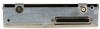
3.4 Weight and Balance Weight and balance computation is required after the installation of the GTX 33. Follow the guidelines as established in AC 43.13-1B, Chapter 10, Section 2. Make appropriate entries in the equipment list indicating items added, removed or relocated along with the date accomplished. Include your name and certificate number in the aircraft records. Section 1.5.1 identifies the weight of the new GTX 33 equipment and Figure C-1 in Appendix C shows the center of gravity. 3.5 Electrical Load Analysis An electrical load analysis should be completed on each aircraft prior to installation in accordance with AC43.13-1B, Chapter 11. Use the following values for computation: Table 3-3. Unit Power Loads GTX 33 Input GTX 33 Main Power 14 VDC Typical Max. 1.6 A 3.1 A 28 VDC Typical 0.85 A Max. 1.6 A 3.6 Final Installation For final installation and assembly, refer to the outline and installation drawings shown in Appendix C of this manual. 1. Assemble the connector backshell as described in Section 3.3. 2. Attach the connector to the rear plate using the screws provided in the connector kit. 3. Mount the unit rack to the main system rack or other suitable mounting location using the provided nutplates or installer supplied screws. 4. Assemble the rear plate into the GTX 33 unit rack using screws provided with the rear plate. 5. Insert the GTX 33 into the rack, noting proper orientation as shown on the installation drawing in Appendix C. CAUTION Do not use excessive force when inserting the GTX 33 into the rack. This may cause damage to occur to the connectors, unit, and/or unit rack. If heavy resistance is felt during installation, stop! Remove the GTX 33 and identify the source of resistance. 6. GTX 33/33D Only: Lock the GTX 33/33D in place using the lever-locking handle. Fasten the handle to the GTX 33/33D body using the provided Phillips screw. (Note that some early GTX 33/ 33D units use a D-ring ¼-turn fastener) CAUTION Start the handle screw into the hole carefully, to avoid cross-threading. Do not apply torque in excess of 14 in-lbs to the handle screw. The application of torque exceeding 14 in-lbs to the screw will damage the LRU case and/or retaining hardware. 7. GTX 33H/33DH Only: Lock the GTX 33H/33DH in place using the install screw. Tighten the screw until the connectors are fully mated and the retaining wedge in the rack is fully mated with the wedge attached to the unit. Tighten to the torque specification shown in Appendix C. 190-00906-00 Rev. F GTX 33 Installation Manual Page 3-5
-
 1
1 -
2
-
3
-
4
-
5
-
6
-
7
-
8
-
9
-
10
-
11
-
12
-
13
-
14
-
15
-
16
-
17
-
18
-
19
-
20
-
21
-
22
-
23
-
24
-
25
-
26
-
27
-
28
-
29
-
 30
30 -
 31
31 -
 32
32 -
 33
33 -
 34
34 -
 35
35 -
 36
36 -
 37
37 -
 38
38 -
 39
39 -
 40
40 -
41
-
42
-
43
-
44
-
45
-
46
-
47
-
48
-
49
-
50
-
51
-
52
-
53
-
54
-
55
-
56
-
57
-
58
-
59
-
60
-
61
-
62
-
63
-
64
-
65
-
66
-
67
-
68
-
69
-
70
-
71
-
72
-
73
-
74
-
75
-
76
-
77
-
78
-
79
-
80
-
81
-
82
-
83
 |
 |
