Garmin GTX 33 Installation Manual - Page 12
Interface Summary, BDS 1, D Mode S Specific Services Protocols MSP Capability Report. - transponder
 |
View all Garmin GTX 33 manuals
Add to My Manuals
Save this manual to your list of manuals |
Page 12 highlights
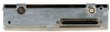
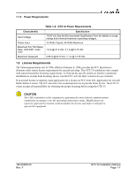
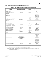
1.6 Interface Summary The GTX 33 provides the following interface connections via the rear connector. See Section 4 and Appendix D for connection details. • Ten (10) encoding altimeter inputs • External IDENT input • External STBY input (useful for dual transponder installations) • External suppression pulse input • Switched power output of up to 1.5 amps (for digital altitude encoder power) • Aircraft power input (14/28 Vdc) • Remote power turn on • Serial airdata or GPS groundspeed input • Serial altitude input (Reduces wire count vs. parallel wire gray code altimeter interface.) • Software update input • Supports Comm-A and Comm-B protocol • Temperature, Altitude Hold and Density Altitude • Digitally recorded voice and discrete warning annunciator activated by Altitude Hold when limits are exceeded • Diversity: GTX 33D is available with the diversity feature • ARINC 429 input The GTX 33 P/N 010-00267-() and GTX 33D 010-00294-() support the following list of Comm-B Definition Subfield (BDS) registers: • BDS (0,0) Air Initiated Comm-B (AICB). • BDS (1,0) Data Link Capability Report. • BDS (1,7) Common Usage Ground Initiated Comm-B (GICB) Capability Report. • BDS (1,8) Mode S Specific Services GICB Capability Report. • BDS (1,9) Mode S Specific Services GICB Capability Report. • BDS (1,D) Mode S Specific Services Protocols (MSP) Capability Report. • BDS (2,0) Aircraft Identification. • BDS (4,0) Selected Vertical Intention • BDS (5,0) Track and Turn Report • BDS (6,0) Heading and Speed Report • BDS (0,6) Extended Squitter surface Position • BDS (0,5) Extended Squitter Airborne Position • BDS (0,8) Extended Squitter Aircraft Identification and Category • BDS (0,9) Extended Squitter Airborne Velocity - Subtypes 1 and 3 • BDS (0,A) Extended Squitter Event Driven Data • BDS (6,1) Emergency/Priority Status • BDS (6,5) Aircraft operational Status GTX 33 Installation Manual Page 1-4 190-00906-00 Rev. F
-
 1
1 -
2
-
3
-
4
-
5
-
6
-
 7
7 -
 8
8 -
 9
9 -
 10
10 -
 11
11 -
 12
12 -
 13
13 -
 14
14 -
 15
15 -
 16
16 -
 17
17 -
18
-
19
-
20
-
21
-
22
-
23
-
24
-
25
-
26
-
27
-
28
-
29
-
30
-
31
-
32
-
33
-
34
-
35
-
36
-
37
-
38
-
39
-
40
-
41
-
42
-
43
-
44
-
45
-
46
-
47
-
48
-
49
-
50
-
51
-
52
-
53
-
54
-
55
-
56
-
57
-
58
-
59
-
60
-
61
-
62
-
63
-
64
-
65
-
66
-
67
-
68
-
69
-
70
-
71
-
72
-
73
-
74
-
75
-
76
-
77
-
78
-
79
-
80
-
81
-
82
-
83
 |
 |
