Garmin Panoptix PS21-TR Forward Trolling Motor Mount Transducer Installation I - Page 2
Installing the Transducer on a Trolling Motor, Shaft
 |
View all Garmin Panoptix PS21-TR Forward Trolling Motor Mount Transducer manuals
Add to My Manuals
Save this manual to your list of manuals |
Page 2 highlights
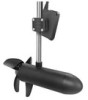
to the motor on the shaft, can prevent proper compass calibration. • To use the compass, you must mount the transducer on the shaft. The compass does not work when you mount the transducer on the motor. Effective Forward Range The transducer has an effective forward range of between five and eight times the depth of the water. For example, in 3 m (10 ft.) of water, the effective forward range is from 15 to 24 m (from 50 to 80 ft.). Water conditions and bottom conditions affect the actual range. Installing the Transducer on a Trolling Motor Shaft Assembling the Trolling Motor Shaft Mount Hardware Use the M6 screws to attach the back of the trolling mount À bracket to the front of the trolling mount bracket around Á Â the trolling motor shaft. 2 Use cable ties to secure the transducer cable to the shaft or other secure location. 3 Route the Ethernet cable to the network switch or to the back of the chartplotter. 4 Route the power cable to a switched or unswitched 10-35 Vdc power source. Adjusting the Transducer Angle on the Trolling Motor Shaft The transducer should be tilted downward for optimal imagery. 1 With the transducer mounted on the trolling motor shaft, tilt the transducer downward between 15 and 30 degrees À Á from the horizontal center of the trolling motor. Installing the Transducer on the Trolling Motor Shaft Mount NOTICE You must secure the transducer cable to the shaft or other secure location during installation. Damage to the transducer cable wire or the cable jacket can cause transducer failure. You should mount the transducer as far from the motor as possible. Placing the transducer too close to the motor can prevent proper compass calibration. Without successful compass calibration, the chartplotter does not display direction and coverage area indicators, but all other features function normally. 1 Use the enclosed knob or mounting bolt to attach the À transducer to the trolling motor mount bracket . Á Â 2 Tighten the knob or mounting bolt so the device does not move during use. 2
-
 1
1 -
 2
2 -
 3
3 -
 4
4
 |
 |
