Garmin Panoptix PS21-TR Forward Trolling Motor Mount Transducer Installation I - Page 3
Installing the Transducer on a Trolling Motor, Connecting the Transducer to Power and the, Garmin
 |
View all Garmin Panoptix PS21-TR Forward Trolling Motor Mount Transducer manuals
Add to My Manuals
Save this manual to your list of manuals |
Page 3 highlights
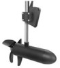
Installing the Transducer on a Trolling Motor Assembling the Trolling Motor Mount Hardware 1 Insert the hose clamp through the slot on the trolling motor À mount . Á 2 Tighten the knob or mounting bolt so the device does not move during use. 2 Slide the hose clamp around the trolling motor. 3 Tighten the hose clamp. Installing the Transducer on a Trolling Motor NOTICE You must secure the transducer cable to the shaft or other secure location during installation. Transducer cable wire damage or damage to the cable jacket can cause transducer failure. 1 Use the enclosed knob or mounting bolt to attach the À transducer to the trolling motor mount bracket . Á Â 2 Secure the transducer cable to the shaft or other secure location. 3 Route the Ethernet cable to the network switch or to the back of the chartplotter. 4 Route the power cable through a switched or unswitched 10 to 35 Vdc power source. Adjusting the Transducer Angle on the Trolling Motor The transducer should be tilted downward for optimal imagery. 1 With the transducer mounted on the trolling motor, tilt the transducer downward between 15 and 30 degrees from À Á the horizontal center of the trolling motor. Connecting the Transducer to Power and the Garmin Marine Network Before you can connect the device to the Garmin Marine Network and power, you must mount the device on the trolling motor. WARNING When connecting the power cable, do not remove the in-line fuse holder. To prevent the possibility of injury or product damage caused by fire or overheating, the appropriate fuse must be in place as indicated in the product specifications. In addition, connecting the power cable without the appropriate fuse in place voids the product warranty. 1 Route the cables using the appropriate tie wraps, fasteners, and sealant to secure the cables along the route, and through any bulkheads or the deck. 2 Install the o-ring and locking collar on the Garmin Marine Network connector. 3 Connect the bare-wire end of the power cable to a 10 to 35 Vdc power source and to the ground. 4 Select an option: • To connect the network cable on a boat equipped with a GMS™ 10 network port expander, connect the network cable to a port on the GMS 10. • To connect the network cable on a boat not equipped with a GMS 10 network port expander, connect the network cable to the network or the Panoptix port on your chartplotter. Cable Routing Grommets When routing cables through your boat, it may be necessary to drill holes to route the cables. Cable routing grommets can be used to cover cable installation holes. The grommets do not create a waterproof seal. If necessary, apply a marine sealant after installation to weatherproof around the grommet and the 3
-
 1
1 -
 2
2 -
 3
3 -
 4
4
 |
 |
