Garmin Reactor 40 Hydraulic Autopilot Installation Instructions PDF - Page 5
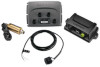
Installing the Pump, Connecting the CCU, Installing the Shadow Drive Valve, Installing the Alarm,
 |
View all Garmin Reactor 40 Hydraulic Autopilot manuals
Add to My Manuals
Save this manual to your list of manuals |
Page 5 highlights
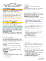
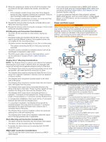
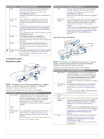
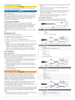
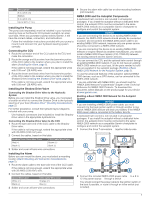
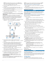
Item Ã Ä Å Æ Description 8 in. (20.3 cm) Battery 8 in. (20.3 cm) Up to 36 ft. (11 m) Installing the Pump The pump (sold separately) must be installed in your hydraulic steering lines so the Reactor 40 Hydraulic autopilot can steer your boat. When you purchase a pump sold by Garmin, it will have the correct cables, connectors, and instructions. Follow the installation instructions provided with your pump to mount it and connect it to your hydraulic steering system correctly. Connecting the CCU 1 Route the connector end of the CCU cable to the ECU and make the connection. 2 Route the orange and blue wires from the bare-wire portion of the CCU cable to the location where you plan to install the alarm (Installing the Alarm, page 5). If the cable is not long enough, extend the appropriate wires with 0.08 mm2 (28 AWG) wire. 3 Route the brown and black wires from the bare-wire portion of the CCU cable to the location where you plan to install the Shadow Drive (Installing the Shadow Drive Valve, page 5). If the cable is not long enough, extend the appropriate wires with 0.08 mm2 (28 AWG) wire. Installing the Shadow Drive Valve Connecting the Shadow Drive Valve to the Hydraulic System Before you can install the Shadow Drive valve, you must select a location at which to connect the Shadow Drive to the hydraulic steering of your boat (Shadow Drive™ Mounting Considerations, page 2). For further assistance, consult the hydraulic-layout diagrams included with your pump. Use hydraulic connectors (not included) to install the Shadow Drive valve in the appropriate hydraulic line. Connecting the Shadow Drive Valve to the CCU 1 Route the bare-wire end of the CCU cable to the Shadow Drive valve. If the cable is not long enough, extend the appropriate wires with 28 AWG (0.08 mm²) wire. 2 Connect the cables, based on this table. Shadow Drive Valve Wire Color Red (+) Black (-) CCU Cable Wire Color Brown (+) Black (-) 3 Solder and cover all bare-wire connections. Installing the Alarm Before you can mount the alarm, you must select a mounting location (Alarm Mounting and Connection Considerations, page 2). 1 Route the alarm cable to the bare-wire end of the CCU cable. If the cable is not long enough, extend the appropriate wires with 28 AWG (0.08 mm2) wire. 2 Connect the cables, based on this table. Alarm Wire Color White (+) Black (-) CCU Cable Wire Color Orange (+) Blue (-) 3 Solder and cover all bare-wire connections. 4 Secure the alarm with cable ties or other mounting hardware (not included). NMEA 2000 and the Autopilot Components A dedicated helm control is not included in all autopilot packages. If you install the autopilot without a dedicated helm control, the autopilot CCU must be connected to the same NMEA 2000 network as a compatible Garmin chartplotter to configure and control the autopilot system. NOTICE If you are connecting this device to an existing NMEA 2000 network, the NMEA 2000 network should already be connected to power. Do not connect the NMEA 2000 power cable to an existing NMEA 2000 network, because only one power source should be connected to a NMEA 2000 network. If you are connecting this device to an existing NMEA 2000 network or engine network by another manufacturer, you should install a NMEA 2000 Power Isolator (010-11580-00) between the existing network and the Garmin devices. You can connect the CCU and the optional helm control through an existing NMEA 2000 network. If you do not have an existing NMEA 2000 network on your boat, all the parts needed to build one are supplied in the autopilot package (Building a Basic NMEA 2000 Network for the Autopilot System, page 5). To use the advanced features of the autopilot, optional NMEA 2000 devices, such as a GPS device, can be connected to the NMEA 2000 network. If you are unfamiliar with NMEA 2000, you should read the "NMEA 2000 Network Fundamentals" chapter of the Technical Reference for NMEA 2000 Products. To download this document, select Manuals on the product page for your device at www.garmin.com. Building a Basic NMEA 2000 Network for the Autopilot System NOTICE If you are installing a NMEA 2000 power cable, you must connect it to the boat ignition switch or through another in-line switch. NMEA 2000 devices will drain your battery if the NMEA 2000 power cable is connected to the battery directly. A dedicated helm control is not included in all autopilot packages. If you install the autopilot without a dedicated helm control, the autopilot CCU must be connected to the same NMEA 2000 network as a compatible Garmin chartplotter to configure and control the autopilot system. 1 Connect the three T-connectors together side-by-side. À 2 Connect the included NMEA 2000 power cable to a 9 to Á 12 Vdc power source through a switch .  à You should connect the power cable to the ignition switch of the boat if possible, or route it through an inline switch (not included). 5
-
 1
1 -
 2
2 -
 3
3 -
 4
4 -
 5
5 -
 6
6 -
 7
7 -
 8
8 -
 9
9 -
 10
10
 |
 |
