Garmin Reactor 40 Hydraulic Autopilot Installation Instructions PDF - Page 6
Configuration
 |
View all Garmin Reactor 40 Hydraulic Autopilot manuals
Add to My Manuals
Save this manual to your list of manuals |
Page 6 highlights
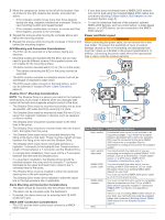
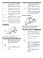
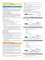
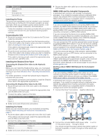
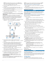
NOTE: The braided drain wire (bare) on the NMEA 2000 power cable must be connected to the same ground as the black wire on the NMEA 2000 power cable. 3 Connect the NMEA 2000 power cable to one of the Tconnectors. 4 Connect one of the included NMEA 2000 drop cables to Ä one of the T-connectors and to the helm control (optional) or to a compatible Garmin chartplotter . Å 5 Connect the other included NMEA 2000 drop cable to the other T-connector and to the CCU . Æ 6 Connect the male and female terminators to each end of Ç the combined T-connectors. Connecting the Autopilot Components to an Existing NMEA 2000 Network A dedicated helm control is not included in all autopilot packages. If you install the autopilot without a dedicated helm control, the autopilot CCU must be connected to the same NMEA 2000 network as a compatible Garmin chartplotter to configure and control the autopilot system. 1 Determine where to connect the CCU and the helm control À (optional) to your existing NMEA 2000 backbone . Á  2 In the location where you plan to connect the CCU, disconnect one side of a NMEA 2000 T-connector from the à network. 3 If necessary, connect a NMEA 2000 backbone extension cable (not included) to the side of the disconnected Tconnector to extend the NMEA 2000 network backbone. 4 Add an included T‑connector for the CCU to the NMEA 2000 backbone by connecting it to the side of the disconnected T‑connector or backbone extension cable. 5 Route the included drop cable to the CCU and to the Ä bottom of the T-connector added in step 4. If the included drop cable is not long enough, you can use a drop cable up to 6 m (20 ft.) long (not included). 6 Connect the drop cable to the CCU and the T-connector. 7 If needed, repeat steps 2 through 6 for the helm control (optional) or a compatible Garmin chartplotter. Connecting Optional NMEA 2000 Devices to the Autopilot System You can use advanced features of the autopilot system by connecting optional NMEA 2000 compatible devices, such as a GPS device, to the NMEA 2000 network. NOTE: You can connect optional devices that are not NMEA 2000 compatible to the helm control through NMEA 0183 (NMEA 0183 Connection Considerations, page 7). 1 Add an additional T-connector (not included) to the NMEA 2000 network. 2 Connect the optional NMEA 2000 device to the T-connector by following the instructions provided with the device. Bleeding the Hydraulics NOTICE This is a general procedure for bleeding a hydraulic steering system. Refer to the instructions provided by the manufacturer of the steering system for more-specific information about bleeding the system. Before you bleed the hydraulic system, you should verify that all hose connections are complete and fully tightened. 1 Select an option: • If the helm reservoir contains insufficient fluid, fill it as needed. • If the helm reservoir contains excess fluid, remove the excess to avoid fluid overflow during the bleeding process. 2 Insert a bypass hose between the cylinder bleed ports. TIP: If you use a clear plastic hose for this bypass, you can observe air bubbles during the bleeding processes. 3 Manually steer the helm fully to port. 4 Open both bypass valves at the cylinder fittings. 5 Manually turn the helm slowly to port over three minutes. TIP: You can stop turning when you no longer see air moving through the bypass hose. 6 Turn on the autopilot system and disable the Shadow Drive. You can refer to the autopilot system documentation for more information on disabling the Shadow Drive. 7 Hold (port) on the helm control for at least 10 seconds. TIP: You can stop holding when you no longer see air moving through the bypass hose. 8 Close both bypass valves at the cylinder fittings. 9 If necessary, add fluid to the helm reservoir. 10Repeat steps 3 through 9 for the starboard side. 11Hold (port) on the helm control until steering stops and Hydraulic Pump Stall is shown on the helm control. 12Hold (starboard) on the helm control until steering stops and Hydraulic Pump Stall is shown on the helm control. 13Select an option: • If Hydraulic Pump Stall is not shown within 2 to 3 seconds after the cylinder stops, repeat steps 1-13 to bleed the system again. • If Hydraulic Pump Stall is shown within 2 to 3 seconds after the cylinder stops, the system bleed completed successfully. After hydraulic bleeding is complete, you can re-enable the Shadow Drive. Corrosion Blocker NOTICE To ensure the long life of all parts, apply corrosion blocker to the pump at least twice yearly. A marine-rated corrosion blocker should be applied to the pump after all hydraulic and electrical connections are made and the hydraulic system has been bled. Configuration The autopilot must be configured and tuned to your boat dynamics. You can use the Dockside Wizard and the Sea Trial 6
-
 1
1 -
 2
2 -
 3
3 -
 4
4 -
 5
5 -
 6
6 -
 7
7 -
 8
8 -
 9
9 -
 10
10
 |
 |
