Gateway EC14 Service Guide - Page 63
Main Unit Disassembly Process - keyboard replacement
 |
View all Gateway EC14 manuals
Add to My Manuals
Save this manual to your list of manuals |
Page 63 highlights
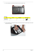
Main Unit Disassembly Process IMPORTANT: Cable paths and positioning may not represent the actual model. During the removal and replacement of components, ensure all available cable channels and clips are used and that the cables are replaced in the same position. NOTE: The product previews seen in the disassembly procedures may not represent the final product color or configuration. Main Unit Disassembly Flowchart Remove External Modules before proceeding Remove Keyboard Remove Upper Cover Remove Button Board Remove LCD Module Remove I/O Board Remove Bluetooth Module Remove LED Board Remove Mainboard Remove Speaker Module Remove CRT Board Remove Thermal Module Remove RTC Battery Chapter 3 53
-
 1
1 -
2
-
3
-
4
-
5
-
6
-
7
-
8
-
9
-
10
-
11
-
12
-
13
-
14
-
15
-
16
-
17
-
18
-
19
-
20
-
21
-
22
-
23
-
24
-
25
-
26
-
27
-
28
-
29
-
30
-
31
-
32
-
33
-
34
-
35
-
36
-
37
-
38
-
39
-
40
-
41
-
42
-
43
-
44
-
45
-
46
-
47
-
48
-
49
-
50
-
51
-
52
-
53
-
54
-
55
-
56
-
57
-
 58
58 -
 59
59 -
 60
60 -
 61
61 -
 62
62 -
 63
63 -
 64
64 -
 65
65 -
 66
66 -
 67
67 -
 68
68 -
69
-
70
-
71
-
72
-
73
-
74
-
75
-
76
-
77
-
78
-
79
-
80
-
81
-
82
-
83
-
84
-
85
-
86
-
87
-
88
-
89
-
90
-
91
-
92
-
93
-
94
-
95
-
96
-
97
-
98
-
99
-
100
-
101
-
102
-
103
-
104
-
105
-
106
-
107
-
108
-
109
-
110
-
111
-
112
-
113
-
114
-
115
-
116
-
117
-
118
-
119
-
120
-
121
-
122
-
123
-
124
-
125
-
126
-
127
-
128
-
129
-
130
-
131
-
132
-
133
-
134
-
135
-
136
-
137
-
138
-
139
-
140
-
141
-
142
-
143
-
144
-
145
-
146
-
147
-
148
-
149
-
150
-
151
-
152
-
153
-
154
-
155
-
156
-
157
-
158
-
159
-
160
-
161
-
162
-
163
-
164
-
165
-
166
-
167
-
168
-
169
-
170
-
171
-
172
-
173
-
174
 |
 |

Chapter 3
53
Main Unit Disassembly Process
IMPORTANT:
Cable paths and positioning may not represent the actual model. During the removal and
replacement of components, ensure all available cable channels and clips are used and that the cables are
replaced in the same position.
NOTE:
The product previews seen in the disassembly procedures may not represent the final product color or
configuration.
Main Unit Disassembly Flowchart
Remove External
Modules before
proceeding
Remove
Mainboard
Remove
LCD Module
Remove
Keyboard
Remove
Upper Cover
Remove
Thermal Module
Remove
Bluetooth Module
Remove
Speaker Module
Remove
I/O Board
Remove
RTC Battery
Remove
LED Board
Remove
Button Board
Remove
CRT Board