Gateway ML6227q 8511725 - Gateway Service Guide - Page 39
Turn the notebook over so the bottom is facing up, then replace the keyboard screws, removed
 |
View all Gateway ML6227q manuals
Add to My Manuals
Save this manual to your list of manuals |
Page 39 highlights
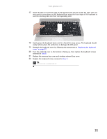
www.gateway.com 17 Insert the tabs on the front edge of the keyboard into the slot under the palm rest. You may need to press down on the keyboard keys along the front edge of the keyboard to seat the retaining tabs into their corresponding slots. 18 Gently press the keyboard down until it is flat all the way across. The keyboard should easily fall into place. Be careful not to damage the LCD panel. 19 Reattach the keyboard cover by following the instructions in "Replacing the keyboard cover" on page 29. 20 Turn the notebook over so the bottom is facing up, then replace the keyboard screws removed in Step 8. 21 Replace the memory bay cover and wireless network bay cover. 22 Replace the keyboard screw removed in Step 3. Tip The screw hole is marked with a K. 35
-
 1
1 -
2
-
3
-
4
-
5
-
6
-
7
-
8
-
9
-
10
-
11
-
12
-
13
-
14
-
15
-
16
-
17
-
18
-
19
-
20
-
21
-
22
-
23
-
24
-
25
-
26
-
27
-
28
-
29
-
30
-
31
-
32
-
33
-
 34
34 -
 35
35 -
 36
36 -
 37
37 -
 38
38 -
 39
39 -
 40
40 -
 41
41 -
 42
42 -
 43
43 -
 44
44 -
45
-
46
-
47
-
48
-
49
-
50
-
51
-
52
-
53
-
54
-
55
-
56
-
57
-
58
-
59
-
60
-
61
-
62
-
63
-
64
-
65
-
66
-
67
-
68
-
69
-
70
-
71
-
72
-
73
-
74
-
75
-
76
-
77
-
78
 |
 |
