GE 6155 Installation Instructions - Page 2
Mounting Without the Swivel, Bracket, Mounting With the Swivel Bracket, Masking
 |
UPC - 046188009565
View all GE 6155 manuals
Add to My Manuals
Save this manual to your list of manuals |
Page 2 highlights
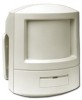
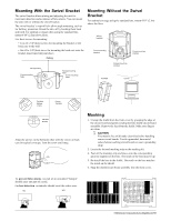
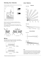
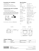
Mounting With the Swivel Bracket The swivel bracket allows aiming and adjusting the unit for maximum detection and avoidance of false alarms. You can mount the unit with or without the swivel bracket. The swivel bracket’s snap-off tabs allow angle mounting, such as for hallway protection. Break the tabs off by bending them back and forth. For optimal coverage when using the standard lens, mount 6'10" (2.1m) above floor. Use these screws for mounting: • Two #6 x 3/4"(2cm) screws for mounting the bracket or the back case to the wall • One #8 x 3/4"(2cm) screw for mounting the back case onto the bracket (insert into ball joint shoe) Ceiling Mounting Without the Swivel Bracket For optimal coverage using the standard lens, mount 6'10" (2.1m) above the floor. Wiring knockout Corner mounting knockout 15 10 5 0 5 10 10 5 0 5 10 Corner mounting knockout Wiring hole Corner mounting holes Flat wall mounting holes Corner mounting holes Flat wall mounting knockout Flat Wall Corner Flat Wall Hallway (1 tab) Corner Two tabs Flat Wall No tabs Align the arrows on the ball joint shoe with the zeroes on back case for typical coverage. Turn the screw until snug. Masking 1. Unsnap the shield from the front cover by grasping the edge of the circuit board and gently rotating the lens shield/circuit board assembly. Remove the lens from the shield. Make sure fingers are clean. CAUTION You must be free of all static electricity before handling sensor circuit boards. Touch a grounded, bare metal suface before touching circuit boards or wear a grounding strap. 2. Locate the lettered masking strip on the masking kit. 4. Peel off the masking strip and press onto the corresponding grooved segment on the lens. The notch of the lens must be up. 5. Re-install the lens in the shield. The notch on the lens matches the notch on the shield. 6. Snap the shield/circuit board assembly into the front cover. To prevent false alarms, no part of an unwanted “hotspot” should enter any part of a zone. For best detection, an intruder should cross the entire zone. NO YES L J G E C A C WV U S R Q O NM 2 6150 Extended Temperature Series SharpShooter PIR
-
 1
1 -
 2
2 -
 3
3 -
 4
4
 |
 |