GE GTDP301ELWS Installation Instructions - Page 3
Warning, Warning - installation
 |
View all GE GTDP301ELWS manuals
Add to My Manuals
Save this manual to your list of manuals |
Page 3 highlights
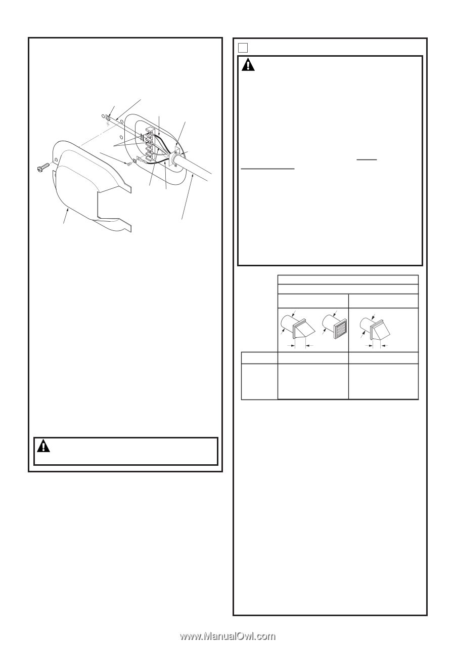
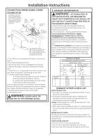
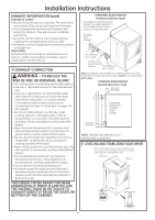
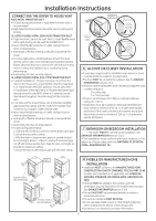
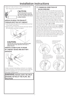
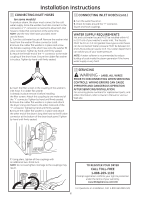
Installation Instructions CONNECTING DRYER USING 3-WIRE CONNECTION IF REQUIRED, BY LOCAL CODE, INS TALL EXTERNAL GROUND (NOT PROVIDED) TO GROUNDED ME TAL, COLD WATER PIPE, OR OTHER ESTABLISHED GROUND DETERMINED BY A QUALIFIED ELECTRICIAN. GREEN GROUND SCREW GROUND STRAP HOT WIRE STRAIN RELIEF BRACKET L1 SCREWS (3) L2 3/4", UL RECOGNIZED STRAIN RELIEF NEUTRAL (White) HOT WIRE COVER 3 #10 AWG MINIMUM COPPER CONDUCTORS OR 120/240V 30A POWER SUPP LY CORD KIT MARKED FOR USE WITH D RYERS & PROVIDED WITH CLOSED LOOP OR SPADE TERMINALS WITH UPTURNED ENDS (NOT SUPPLIED). 1. Turn off the circuit breaker(s) (30 amp) or remove the dryer's circuit fuse at the electrical box. 2. Be sure the dryer cord is unplugged from the wall. 3. Remove the power cord cover located at the lower back. 4. Install 3/4 in. UL recognized strain relief to power cord entry hole. Bring power cord through strain relief. 5. Connect power cord as follows: A. Connect the 2 hot lines to the outer screws of the terminal block (marked L1 and L2). B. Connect the neutral (white) line to the center of the terminal block (marked N). 6. Be sure ground strap is connected to neutral (center) terminal of block and to green ground screw on cabinet rear. Tighten all terminal block screws (3) completely. 7. Properly secure power cord to strain relief. 8. Reinstall the cover. WARNING: NEVER LEAVE THE COVER OFF OF THE TERMINAL BLOCK. 3 EXHAUST INFORMATION WARNING - IN CANADA AND IN THE UNITED STATES, THE REQUIRED EXHAUST DUCT DIAMETER IS 4 IN (102mm). DO NOT USE DUCT LONGER THAN SPECIFIED IN THE EXHAUST LENGTH TABLE. Using exhaust longer than specified length will: • Increase the drying times and the energy cost. • Reduce the dryer life. • Accumulate lint, creating a potential fire hazard. The correct exhaust installation is YOUR RESPONSIBILITY. Problems due to incorrect installation are not covered by the warranty. Remove and discard existing plastic or metal foil transition duct and replace with UL listed transition duct . The MAXIMUM ALLOWABLE duct length and number of bends of the exhaust system depends upon the type of duct, number of turns, the type of exhaust hood (wall cap), and all conditions noted below. The maximum duct length for rigid metal duct is shown in the table below. EXHAUST LENGTH RECOMMENDED MAXIMUM LENGTH Exhaust Hood Types Recommended Use only for sho rt run installations 4" DIA. 4" DIA. 4" DIA. No. of 90º Elb ows 0 1 2 3 4 4" Rigid Metal 90 Feet 60 Feet 45 Feet 35 Feet 25 Feet 2-1/2" Rigid Metal 60 Feet 45 Feet 35 Feet 25 Feet 15 Feet EXHAUST SYSTEM CHECK LIST HOOD OR WALL CAP • Terminate in a manner to prevent back drafts or entry of birds or other wildlife. • Termination should present minimal resistance to the exhaust air flow and should require little or no maintenance to prevent clogging. •Never install a screen in or over the exhaust duct. This could cause lint build up. • Wall caps must be installed at least 12 in. above ground level or any other obstruction with the opening pointed down. SEPARATION OF TURNS For best performance, separate all turns by at least 4 ft. of straight duct, including distance between last turn and exhaust hood. TURNS OTHER THAN 90º • One turn of 45º or less may be ignored. • Two 45º turns should be treated as one 90º turn. • Each turn over 45º should be treated as one 90º turn. 3
-
 1
1 -
 2
2 -
 3
3 -
 4
4 -
 5
5 -
 6
6 -
 7
7 -
 8
8
 |
 |