GE GTDP301ELWS Installation Instructions - Page 7
Caution
 |
View all GE GTDP301ELWS manuals
Add to My Manuals
Save this manual to your list of manuals |
Page 7 highlights
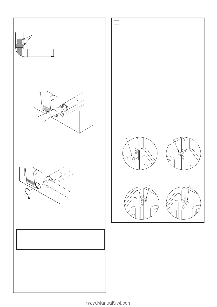
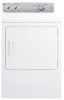
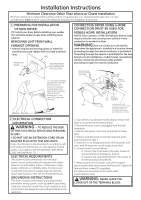
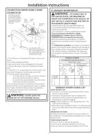
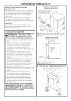
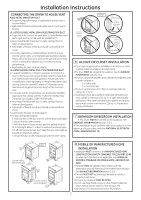
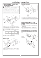
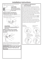
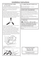
Installation Instructions • Apply duct tape as shown on the joint between the dryer internal duct and the elbow. DUCT TAPE CAUTION: Internal duct joints must be secured with tape, otherwise they may separate and cause a safety hazard. ADDING ELBOW FOR EXHAUST THROUGH BOTTOM OF CABINET • Insert the elbow through the rear opening and connect it to the dryer internal duct. • Apply duct tape on the joint between the dryer internal duct and elbow, as shown on page 6. 10 CHANGING DIRECTION OF DOOR OPENING 1. Open the door and remove the filler plugs opposite the hinges. With the door completely open, remove the bottom screws from each hinge on the dryer face. Insert these screws about half way into the TOP holes, for each hinge on the opposite side (where you removed the filler plugs). Apply firm pressure to get the screw started. 2. Loosen the top screws from each hinge on the dryer face half way. With one hand holding the top of the door and the other hand holding the bottom, remove the door from the dryer by lifting it UP and OUT. 3. Rotate the door 180º. Insert the door on the opposite side of the opening by moving the door IN and DOWN until the top hinge and the bottom hinge are resting on the top screws inserted in step 1. 4. Remove the remaining screws from the side of the opening from which the door was removed. With these screws secure each hinge at the bottom. Tighten the two top screws on each hinge. Reinsert the plastic plugs on the side from which the door was removed. CAUTION: Internal duct joints must be secured with tape, otherwise they may separate and cause a safety hazard. ADDING COVER PLATE TO REAR OF CABINET (SIDES AND BOTTOM EXHAUST) REMOVE THE BOTTOM SCREW FROM EACH HINGE ON THE DRYER FACE LOOSEN THE TOP SCREWS FROM EACH HINGE ON THE DRYER FACE HALF WAY MOVE THE DOOR IN AND DOWN UNTIL THE TOP HINGE AND THE BOTTOM HINGES ARE RESTING ON THE TOP SREWS INSERTED IN STEP 1 SECURE EACH HINGE AT THE BOTTOM AND TIGHTEN THE TWO TOP SCREWS OF EACH HINGE PL ATE (KIT WE1M454) Connect standard metal elbows and ducts to complete the exhaust system. Cover back opening with a plate (Kit WE1M454) available from your local service provider. Place dryer in final location. WARNING-NEVER LEAVE THE BACK OPENING WITHOUT THE PLATE. (Kit WE1M454) 7
-
 1
1 -
 2
2 -
 3
3 -
 4
4 -
 5
5 -
 6
6 -
 7
7 -
 8
8
 |
 |