GE GTDP301ELWS Installation Instructions - Page 4
Warning - installation manual
 |
View all GE GTDP301ELWS manuals
Add to My Manuals
Save this manual to your list of manuals |
Page 4 highlights
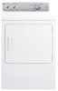
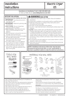
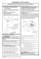
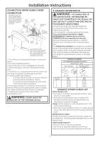
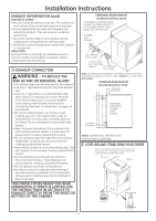
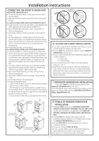
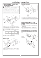
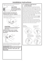
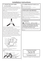
Installation Instructions EXHAUST INFORMATION (cont) SEALING OF JOINTS • All joints should be tight to avoid leaks. The male end of each section of duct must point away from the dryer. • Do not assemble the ductwork with fasteners that extend into the duct. They will serve as a collection point for lint. • Duct joints can be made air and moisture-tight by wrapping the overlapped joints with duct tape. • Horizontal runs should slope down toward the outdoors ½ inch per foot INSULATION Duct work that runs through an unheated area or is near air conditioning should be insulated to reduce condensation and lint build-up. 4 EXHAUST CONNECTION WARNING - TO REDUCE THE RISK OF FIRE OR PERSONAL INJURY: • This clothes dryer must be exhausted to the outdoors. • Use only 4" rigid metal ducting for the home exhaust duct . • Use only 4" rigid metal or UL-listed flexible metal (semi-rigid or foil-type) duct to connect the dryer to the home exhaust duct. It must be installed in accordance with the instructions found in "Connecting The Dryer To House Vent" on page 5 of this manual. • Do not terminate exhaust in a chimney, a wall, a ceiling, gas vent, crawl space, attic, under an enclosed floor, or in any other concealed space of a building. The accumulated lint could create a fire hazard. • Never terminate the exhaust into a common duct with a kitchen exhaust system. A combination of = grease and lint creates a potential fire hazard. • Do not use duct longer than specified in the exhaust length table. Longer ducts can accumulate lint, creating a potential fire hazard. • Never install a screen in or over the exhaust duct. This will cause lint to accumulate, creating a potential fire hazard. • Do not assemble ductwork with any fasteners that extend into the duct. These fasteners can accumulate lint, creating a potential fire hazard. • Do not obstruct incoming or exhausted air. • Provide an access for inspection and cleaning of the exhaust system, especially at turns and joints. Exhaust system shall be inspected and cleaned at least once a year. THIS DRYER COMES READY FOR REAR EXHAUSTING. IF SPACE IS LIMITED, USE THE INSTRUCTIONS IN SECTION 9 TO EXHAUST DIRECTLY FROM THE SIDES OR BOTTOM OF THE CABINET. STANDARD REAR EXHAUST (Vented at all floor level) FOR STRAIGHT LINE INSTALLATION, CONNECT THE DRYER EXHAUST TO THE EXTERNAL EXHAUST HOOD USING DUCT TAPE OR CLAMP. EXTERNAL DUCT OPENING DUCT TAPE OR DUCT CLAMP 4" METAL DUCT (CUT TO PROPER LENGTH) DUCT TAPE OR DUCT CLAMP NOTE: WE STRONGLY RECOMMEND SOLID METAL EXHAUST DUCTING. HOWEVER, IF FLEXIBLE DUCTING IS USED IT MUST BE UL-LISTED METAL NOT PLASTIC. STANDARD REAR EXHAUST (Vented above floor level) ELBOW HIGHLY RECOMMENDED RECOMMENDED CONFIGUR A TION TO MINIMIZE EXHAUST BLOCKAGE. ELBOW HIGHLY RECOMMENDED NOTE: ELBOWS WILL PREVENT DUCT KINKING AND COLLAPSING. 5 LEVELING AND STABILIZING YOUR DRYER STAND THE DRYER UPRIGHT NEAR THE FINAL LOCATION AND ADJUST THE 4 LEVELING LEGS, AT THE CORNERS, TO ENSURE THAT THE DRYER IS LEVEL FROM SIDE TO SIDE AND FRONT TO REAR. LEVEL FRONT-TO-BACK. LEVEL SIDE-TO-SIDE. 4 LEVELING LEGS 2 ANTI-TIP LEGS 4
-
 1
1 -
 2
2 -
 3
3 -
 4
4 -
 5
5 -
 6
6 -
 7
7 -
 8
8
 |
 |