GE JV348LSS Use and Care Manual - Page 10
Remove Exhaust Adaptor, Remove Filter, Reverse The Baffle For Ducted, Installations Only, Remove
 |
UPC - 084691143710
View all GE JV348LSS manuals
Add to My Manuals
Save this manual to your list of manuals |
Page 10 highlights
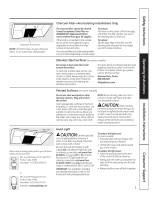
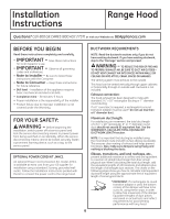
Installation Instructions 2 REMOVE EXHAUST ADAPTOR If exhausting/venting using the 31⁄4″ x 10″ rectangular duct-optional for JV247, JV248, JV338, JV347, JV348 and JV367 models only: Remove the exhaust adaptor from the inside of the hood. Set it aside along with its mounting screws. 5 REMOVE WIRING COVER Remove the wiring cover from inside the hood. Set the cover and its mounting screws aside. Wiring cover 31⁄4″ x 10″ rectangular exhaust adaptor and screws 3 REMOVE FILTER Remove the shipping tape holding the metal grease filter in place. Pull down on the center of the front edge of the filter. The filter will then slip out of the retaining tabs on the back. 6 REMOVE WIRING KNOCKOUT Remove either the top or the back wiring knockout as needed and install an approved strain relief clamp. Top knockout Back knockout Strain relief clamp Strain relief clamp Metal grease filter 4 REVERSE THE BAFFLE FOR DUCTED INSTALLATIONS ONLY (JV247, JV248, JV347, JV348 and JV367 models) If the hood is to be recirculated, skip to the next step. Remove the baffle from the top of the hood. Reinstall the baffle so the short side marked "VENTED" is visible. The long side of the baffle should be inside the hood. "VENTED" is visible 7 REMOVE DUCT KNOCKOUT If recirculating, non-vented ductless (JN327 and RN328, and optional for JV247, JV248, JV347, JV348 and JV367 models only), skip to Step 11 D and proceed. Using a flat-blade screwdriver, remove the appropriate duct knockout from the top or back of the hood. 31⁄4″ x 10″ Rectangular vertical discharge. Remove top rectangular duct knockout only. 7″ Round vertical discharge. Remove circular duct knockout only. 31⁄4″ x 10″ Rectangular horizontal discharge. Remove rear rectangular duct knockout only. 10
-
 1
1 -
2
-
3
-
4
-
 5
5 -
 6
6 -
 7
7 -
 8
8 -
 9
9 -
 10
10 -
 11
11 -
 12
12 -
 13
13 -
 14
14 -
 15
15 -
16
 |
 |
