GE NX548E Installation Instructions - Page 3
Wiring, DIP switch settings, Power up - receiver
 |
UPC - 782136713930
View all GE NX548E manuals
Add to My Manuals
Save this manual to your list of manuals |
Page 3 highlights
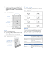
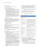
3 9. To install the circuit board onto the back plate (Figure 7), insert the antennas into the antenna shrouds, then gently slide the top of the circuit board under the two top latches, and snap the circuit board in at the bottom latch to secure it in place. Figure 7. Circuit board and back plate Antenna shrouds Top latches Circuit board Back plate DIP switches ON ECE 1 2 3 4 Wiring terminals LEDs Bottom latch Wiring To wire the receiver, do the following: 1. Remove power (if applied) from the control panel.Use 22- gauge, or larger, stranded wire to connect the +12, GND, and DATA terminals on the receiver (Figure 8) to the power, common, and data terminals on the control panel. Figure 8. Receiver wiring connections and LEDs + 12 (to panel POS) GND (to panel COM) DATA (to panel DATA) Green (power) LED Red (data) LED Red (not used) LED DIP switch settings The DIP switches (Figure 7) on the circuit board are used to set the receiver module number. Use Table 2 to set the DIP switches to the desired module number. Table 2. DIP switch settings Module number 32 Module number 33 ON EDG 12 34 ON EDG 12 34 Module number 34 Module number 35 (default) ON EDG 12 34 Module number 36 ON EDG 12 34 Module number 37 ON EDG 12 34 Module number 38 ON EDG 12 34 Module number 39 ON EDG 12 34 ON EDG 12 34 Power up When you apply power to the control panel, the green (power) LED on the receiver (Figure 8) blinks for approximately 10 seconds. Table 3 describes the receiver status based on LED conditions.The lower red LED at the bottom of the receiver (Figure 8) may emit a dim glow, but is not used as an indicator. Table 3. LED indications Green (power) LED status Power-up blinks Off Short blink on Long blink on Meaning LED blinks represent Product Version Number (PVN). Long blink on is 1, short blink on is 0. PVN is in binary, from most significant to least significant bit. No packets from sensors being received. Receiver received a valid packet from an unknown sensor. Receiver received a valid packet from an enrolled sensor. Red (data) LED status Off Short blink on Meaning No data communication with the control panel. Check wiring and power source. Normal data communication with the control panel.
-
 1
1 -
 2
2 -
 3
3 -
 4
4 -
 5
5 -
 6
6 -
 7
7 -
 8
8 -
 9
9 -
10
-
11
-
12
 |
 |
