GE NX548E Installation Instructions - Page 4
Programming - installation
 |
UPC - 782136713930
View all GE NX548E manuals
Add to My Manuals
Save this manual to your list of manuals |
Page 4 highlights
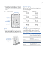
4 NetworX NX-548E Receiver Installation Instructions Programming This section describes how to program the units. Programming guidelines Use the following programming guidelines: • NX-4 and NX-6 control panels can have receivers added with zones that overlap those contained in the control panel. No hardware expanders can be used. • NX-8 control panels can have expansion zones (hardwire or wireless) set the same as those contained in the control panel. To do this you must disable the onboard control panel zones in panel location 37. All zone expansion modules must not overlap any blocks of 8 zones. • All other control panels can have wireless zones added to any zone. If a hardwire input (on either the control panel or hardwire expander) is also present on the same zone as an enabled wireless zone, the wireless transmitter takes priority. Transmitter programming When programming wireless transmitters into the receiver, you can set various options and partitions for each transmitter. These settings appear in segments of each programming location. Use Table 5 on page 7 to record zone assignments and settings. Be sure to circle where each zone resides: RM. Receiver module HE. Hardwire expander P. Panel This gives you all the programming information in one place to facilitate the programming process. Zone locations 1 to 192 Zone locations 1 to 192 are not numbered in Table 5 on page 7 since these locations vary depending on location 194, Receiver zone bank setting. Note: The default settings shown for segments 1 and 2 in the first zone location apply to all zone locations. Add transmitters LCD touchpads will display instructions when accomplishing tasks. To add transmitters, do the following: 1. Enter * 8 at the keypad. On LED touchpads, the five function lights start flashing. 2. Enter the program code (factory default is 9 7 1 3). On LED touchpads, the service light flashes and the five function lights change from flashing to on steady. 3. Enter the DIP switch setting module number and press #. On LED touchpads, the Armed LED turns on, indicating the control panel is waiting for a programming location entry. 4. For new installations, enter 9 1 0 # to load factory defaults and clear any unwanted information in memory. 5. For new installations, set the receiver zone bank setting in location 194 to determine the starting zone number for the specific receiver. This applies only to NX-8E. This must be set before learning sensors. For example, if location 194 is set to 3, the first available location is 25. The total number of available locations depends on the zone limits for both the panel and receiver. 6. Enter 0 # to enter the sensor learning location. On LED touchpads, the Ready LED turns on and the Armed LED turns off. 7. Enter the zone number (1 through 192) and press *. Three beeps from the keypad indicate an entry error. This occurs if you enter a transmitter number that is not within the receiver's zone block or if the location already has a sensor learned into it. Note: If you change your mind about your entry, terminate programming by entering 0 # 0 * and start over at step 6. 8. Trip the desired transmitter (within 250 seconds) as described in Table 4. Listen for the ding dong for confirmation. Note: For specific instructions on tripping a transmitter, consult the transmitter's manual. Table 4. Tripping transmitters Transmitter Action Door/window, shock, glass guard, freeze, UFT (Universal Fire Transmitter) Activate tamper switch by removing cover. Door/window with external contact Activate tamper switch by removing cover. Feature 4-Input option 1, must be on. Recessed door/window Activate tamper switch by removing circuit board until tamper switch is exposed. Micro door/window and Refer to the installation instructions for the Micro recessed door/window specific sensor for activation information. SlimLine door/window Remove cover, then press the button on the top of the sensor, or activate the tamper switch by removing the cover. PIR Activate tamper switch by removing back plate from PIR. Smoke detector without tamper switch Press and hold the test button. Smoke detector with tamper Trip the tamper switch. Feature 4-Input switch option 1, must be on. Heat detector Press, then release the tamper switch. Single button panic Press and hold the button. Dual button panic Press and hold both buttons together. Keyfobs Press and hold the lock and unlock buttons together. Repeater Press, then release the tamper switch. 9. To program remaining transmitters, repeat steps 6 to 8. 10. To exit program mode, press EXIT EXIT. 11. Confirm that the zone types and partition assignments are set correctly in the control panel. Refer to the control panel installation manual for instructions on how to set zone types and partition assignments. Note: When an 80-bit device is added, Feature 6 of Segment 1 (see Table 5 on page 7) is turned on. But when a 63-bit device is added on a zone location that previously had an 80-bit device, make sure to turn off Feature 6 of Segment 1.
-
 1
1 -
 2
2 -
 3
3 -
 4
4 -
 5
5 -
 6
6 -
 7
7 -
 8
8 -
 9
9 -
 10
10 -
11
-
12
 |
 |
