GE PVM9215SKSS Installation Instructions - Page 4
HOOD EXHAUST, Installation Instructions
 |
View all GE PVM9215SKSS manuals
Add to My Manuals
Save this manual to your list of manuals |
Page 4 highlights
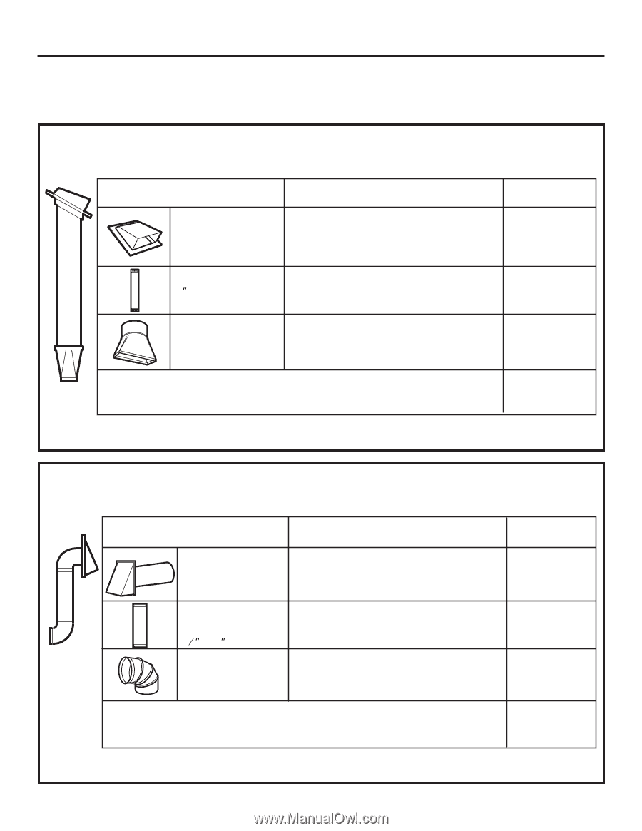
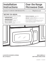
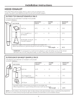
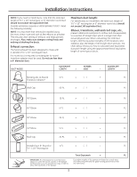
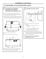
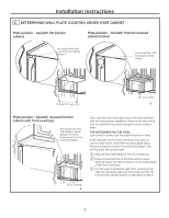
Installation Instructions HOOD EXHAUST NOTE: Read these next two pages only if you plan to vent your exhaust to the outside. If you plan to recirculate the air back into the room, proceed to page 6. OUTSIDE TOP EXHAUST (EXAMPLE ONLY) The following chart describes an example of one possible ductwork installation. DUCT PIECES EQUIVALENT LENGTH x NUMBER USED EQUIVALENT = LENGTH Roof Cap 24 Ft. x (1) = 24 Ft. 12 Ft. Straight Duct (6s Round) 12 Ft. x (1) = 12 Ft. Rectangular-to-Round 5 Ft. Transition Adaptor* x (1) = 5 Ft. Equivalent lengths of duct pieces are based on actual tests and reflect requirements for good venting performance with any vent hood. Total Length = 41 Ft. * IMPORTANT: If a rectangular-to-round transition adaptor is used, the bottom corners of the damper will have to be cut to fit, using the tin snips, in order to allow free movement of the damper. OUTSIDE BACK EXHAUST (EXAMPLE ONLY) The following chart describes an example of one possible ductwork installation. DUCT PIECES EQUIVALENT LENGTH* x NUMBER USED EQUIVALENT = LENGTH Wall Cap 40 Ft. x (1) = 40 Ft. 3 Ft. Straight Duct 3 Ft. (31ø4s x 10s Rectangular) x (1) = 3 Ft. 90° Elbow 10 Ft. x (2) = 20 Ft. Equivalent lengths of duct pieces are based on actual tests and reflect requirements for good venting performance with any vent hood. Total Length = 63 Ft. NOTE: For back exhaust, care should be taken to align exhaust with space between studs, or wall should be prepared at the time it is constructed by leaving enough space between the wall studs to accommodate exhaust. 4
-
 1
1 -
 2
2 -
 3
3 -
 4
4 -
 5
5 -
 6
6 -
 7
7 -
 8
8 -
 9
9 -
 10
10 -
11
-
12
-
13
-
14
-
15
-
16
-
17
-
18
-
19
-
20
-
21
-
22
-
23
-
24
-
25
-
26
-
27
-
28
-
29
-
30
-
31
-
32
-
33
-
34
-
35
-
36
-
37
-
38
-
39
-
40
-
41
-
42
-
43
-
44
-
45
-
46
-
47
-
48
 |
 |