GE zgu384nsmss Installation Instructions - Page 15
GE zgu384nsmss - 30" SS GAS COOKTOP NG Manual
 |
UPC - 084691143154
View all GE zgu384nsmss manuals
Add to My Manuals
Save this manual to your list of manuals |
Page 15 highlights
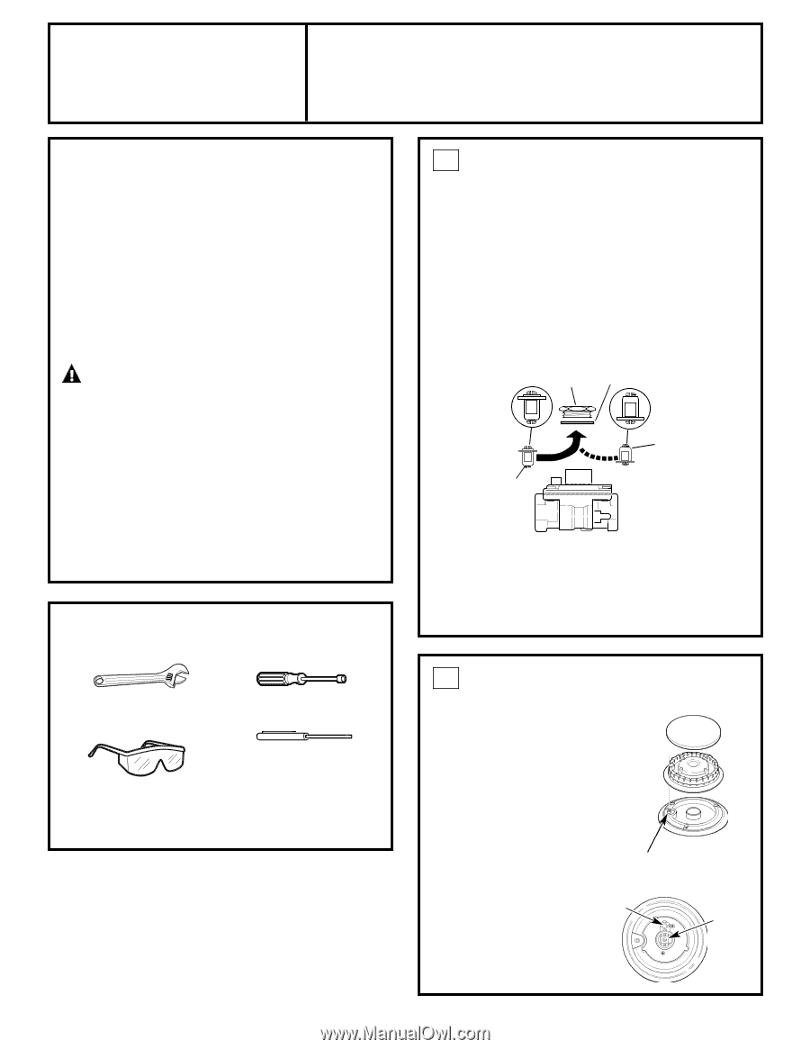
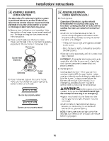
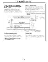
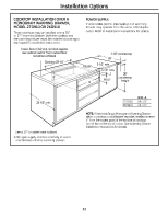
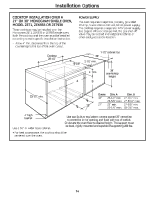
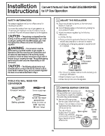
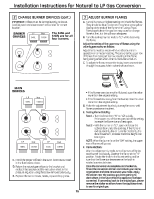
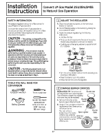
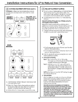
Installation Instructions SAFETY INFORMATION Convert Natural Gas Model ZGU384NSMSS to LP Gas Operation 1 ADJUST THE REGULATOR A. Disconnect all electrical power, at the main circuit breaker or fuse box. B. Shut off the gas supply to the cooktop by closing the manual shut-off valve. C. Adjust the pressure regulator by the following instructions: • Unscrew the cap. • Place your thumb against the flat side of the spring retainer and press down to remove the retainer. • Carefully look at the spring retainer to locate the NAT or LP position. Gasket Cap NAT NAT LP LP The pressure regulator and burner orifices are set for natural gas operation. To convert this cooktop from natural gas operation to LP operation, the regulator and burner orifices must be converted. LP burner orifices are attached to the regulator. - The cooktop, as shipped from the factory, is set for use with its intended gas. If you wish to use your cooktop with the alternate gas, you must first replace the orifices and convert the pressure regulator. - This conversion must be performed by a qualified installer or gas supplier in accordance with the manufacturer's instructions and all codes and requirements of the authority having jurisdiction. Failure to follow instructions could result in serious injury or property damage. The qualified agency performing this work assumes responsibility for the conversion. - The following adjustments must be made before turning on the burner. Failure to do so could result in serious injury. Be sure pressure regulator has been converted as described in Step 1. CAUTION WARNING Spring retainer NAT TOOLS YOU WILL NEED FOR CONVERSION Crescent wrench 7mm nutdriver Pressure regulator • Turn the spring retainer over so that the desired gas is showing on the bottom. • Snap the retainer back into position. • Screw the cap back onto the regulator. 2 CHANGE BURNER ORIFICES Burner cap INSTALLATION TIP: First remove all orifices and then start replacing them. This will help to prevent the possibility that some may not be replaced. Burner A. Remove the burner grates, burner caps and burner heads. head B. Using a 7mm nut driver, remove the top burner orifices. There are two orifices per burner. Burner The main orifice is Spark igniter base located low in the center of the burner, while the Simmer simmer orifice is located Main orifice higher beside the center orifice of the burner. Safety glasses Small flat-head screwdriver (2 to 2.4 mm or 3/32″ tip size, 60 mm long) 15 DOWN FOR OFF CAUTION NAT. position NAT LP LP L.P./propane position
-
 1
1 -
2
-
3
-
4
-
5
-
6
-
7
-
8
-
9
-
 10
10 -
 11
11 -
 12
12 -
 13
13 -
 14
14 -
 15
15 -
 16
16 -
 17
17 -
 18
18 -
 19
19 -
 20
20 -
21
-
22
-
23
-
24
-
25
-
26
-
27
-
28
-
29
-
30
-
31
-
32
-
33
-
34
-
35
-
36
 |
 |