Genie PowerLift Owner's Manual - Page 9
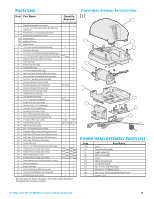
Caution - garage door opener parts
 |
View all Genie PowerLift manuals
Add to My Manuals
Save this manual to your list of manuals |
Page 9 highlights
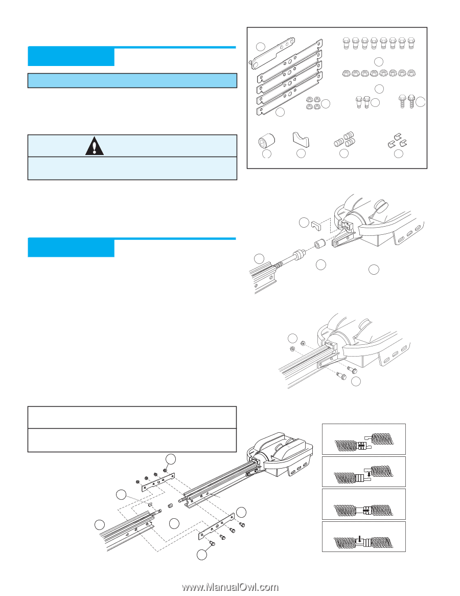
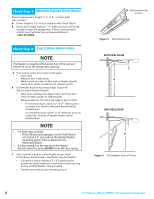
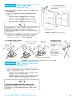
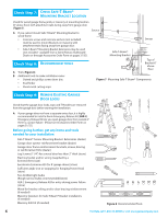
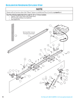
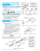
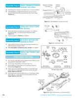
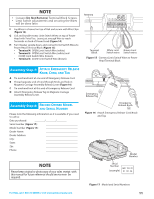
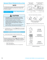
GARAGE DOOR OPENER ASSEMBLY Assembly Step C1H: CONNECT RAIL TO POWER HEAD OPEN BLUE PARTS BAG A Turn Power Head upside down and place on a flat level surface. B Install Bumper (Figure 9). C Install Coupler on Motor Shaft (Figure 9). CAUTION The Drive Screw and Rail Liner can slide out of Rail Sections. Keep Rail Sections level until the Opener is fully assembled. D Connect first Rail Section to Opener Power Head. Connect with 2 (1/4"-20) (yellow) Hex Head Shoulder Bolts and 2 (1/4" -20) Hex Serrated Flange Nuts (Figure 10). Finger-tighten until later. E If you have a 1-piece rail unit, skip Assembly Step 2. Assembly Step C2H: INSTALL REMAINING RAIL SECTIONS A Arrange arrows on Rail Sections to point in same direction and away from Power Head: • Push Middle Drive Screw out about 2" toward Power Head. • Slide Collar over Middle Drive Screw Hook (Figure 11A). • Turn Middle Screw by hand to align Drive Screw Hooks between First and Middle Rail Sections. • Latch two Hooks together and slide Collar over them (Figure 11B) and (Figure 11C). • Snap Clip on Drive Screw next to Collar (Figure11D). B Attach Middle Rail Section to First Rail Section, using 2 Rail Clamps, 4 (5/16"-18) Hex Shoulder Bolts, and 4 (5/16"-18) Hex Head Serrated Flange Nuts onto Bolts (Figure 11). Finger-tighten until later. (Middle Rail Section looks the same on both ends. See page 8.) C Attach End Rail Section to Middle Rail Section following procedures in step A & B. Rail Strap 15 5/16"-18 Hex Head Shoulder Bolts 10 5/16"-18 Hex Serrated Flange Nuts 11 8 2 9 1/4"-20 Hex 1/4"-20 Hex Head Rail Clamps Serrated Flange Nuts Shoulder Bolts (yellow) 16 1/4"-20 Hex Head Bolts 46 Coupler 54 13 14 Bumper Collars + spare Retaining Clips + spare Hardware (blue bag) Bumper (remove backing) 54 First Rail Section 4A Coupler 46 Power Head Assembly 1 Figure 9 Install Bumper, Coupler and 1st Rail Section 8 2 Figure 10 Bolt 1st Rail Section to Power Head NOTE If the Extension Assembly (GSXL8) is needed, attach it per instructions supplied with kit. 11 11A. Slip on collar 11B. Engage Hooks Retaining Clips 14 Middle Rail Section 4B Arrows point toward door 11C. Slide Collar over Hooks Collar 9 Rail Clamps 13 11D. Snap on Retaining Clip 10 Figure 11 Attach Middle Rail Section For Help, call 1-800-35-GENIE or visit www.geniecompany.com 9
-
 1
1 -
2
-
3
-
 4
4 -
 5
5 -
 6
6 -
 7
7 -
 8
8 -
 9
9 -
 10
10 -
 11
11 -
 12
12 -
 13
13 -
 14
14 -
15
-
16
-
17
-
18
-
19
-
20
-
21
-
22
-
23
-
24
-
25
-
26
-
27
-
28
-
29
-
30
-
31
-
32
 |
 |