Gigabyte 7CN700ID Manual
Gigabyte 7CN700ID Manual
 |
View all Gigabyte 7CN700ID manuals
Add to My Manuals
Save this manual to your list of manuals |
Gigabyte 7CN700ID manual content summary:
- Gigabyte 7CN700ID | Manual - Page 1
GA-7CN700ID VIA C7 Processor Motherboard User's Manual Rev. 100 12ME-7CN700ID-1001R * The WEEE marking on the product indicates this product must not be disposed of with user's other household waste and must be handed over - Gigabyte 7CN700ID | Manual - Page 2
Table of Contents GA-7CN700ID Motherboard Layout 3 Block Diagram ...4 Chapter 1 Hardware Installation 5 1-1 Considerations Prior to Installation 5 1-2 10 Chapter 2 BIOS Setup 19 The Main Menu (For example: BIOS Ver. : F2e 20 2-1 Standard CMOS Features 22 2-2 Advanced BIOS Features 24 2-3 - Gigabyte 7CN700ID | Manual - Page 3
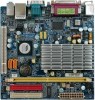
GA-7CN700ID Motherboard Layout COMA VGA MS LPT KB BIOS VIA C7 DDRII BUZZER COMB GA-7CN700ID W83627 ATX VIA CN700 F_USB2 F_USB1 VT6103L AUDIO CD_IN F_AUDIO CODEC PCI VT8237R Plus CLR_CMOS BAT IDE1 IDE2 SATA2 SATA1 F_PANEL SYS_FAN COMC COMD USB LAN JP1 - 3 - - Gigabyte 7CN700ID | Manual - Page 4
(33MHz) VIA C7 Processor VGA Port RJ45 533/400 MHz FSB VIA CN700 533/400 MHz DDRII VT6103L VIA VT8237R Plus LPC BUS 2 Serial ATA BIOS W83627 LPT Port AC97 Link PS/2 KB/Mouse 6 Channel CODEC 6 USB ATA33/66/100/133 Ports IDE Channels COM Ports MIC LINE-IN LINE-OUT - Gigabyte 7CN700ID | Manual - Page 5
instructions below: 1. Please turn off the computer and unplug its power cord. 2. When handling the motherboard motherboard. Installation Notices 1. Prior to installation, please do not remove the stickers on the motherboard the motherboard or have a problem related to the the user manual. 3. Damage - Gigabyte 7CN700ID | Manual - Page 6
chip (10/100 Mbit) Audio Onboard VT1616B CODEC Supports 2 / 4 / 6 channel audio Supports Line In ; Line Out ; MIC CD In connection System fan speed detection BIOS Use of licensed AWARD BIOS Form Factor Mini-ITX form factor; 17.0cm x 17.0cm GA-7CN700ID Motherboard - 6 - - Gigabyte 7CN700ID | Manual - Page 7
can be installed in only one direction. If you are unable to insert the module, please switch the direction. The motherboard supports DDR II memory modules, whereby BIOS will automatically detect memory capacity and specifications. Memory modules are designed so that they can be inserted only in one - Gigabyte 7CN700ID | Manual - Page 8
steps outlined below: 1. Read the related expansion card's instruction document before installing the expansion card into the computer. 2. the computer, if necessary, setup BIOS utility of expansion card from BIOS. 8. Install related driver from the operating system. GA-7CN700ID Motherboard - 8 - - Gigabyte 7CN700ID | Manual - Page 9
, scanner, zip, speaker...etc. have a standard USB interface. Also make sure your OS supports USB controller. If your OS does not supportUSB controller, please contact OS vendor for possible patch or driver upgrade. For more information please contact your OS or device(s) vendors. Line In Devices - Gigabyte 7CN700ID | Manual - Page 10
English 1-6 Connectors Introduction 8 1 9 12 11 2 7 10 6 4 5 3 1) ATX 2) IDE1/ IDE2 3) SATA1 / SATA2 4) SYS_FAN 5) F_PANEL 6) F_AUDIO 7) CD_IN 8) COMB 9) F_USB1 / F_USB2 10) BAT 11) CLR_CMOS 12) JP1 GA-7CN700ID Motherboard - 10 - - Gigabyte 7CN700ID | Manual - Page 11
pin ATX ) With the use of the power connector, the power supply can supply enough stable power to all the components on the motherboard. Before connecting the power connector, please make sure that all components and devices are properly installed. Align the power connector with its proper location - Gigabyte 7CN700ID | Manual - Page 12
information on settings, please refer to the instructions located on the IDE device). Before attaching BIOS setting for the Serial ATA and install the proper driver in order to work properly. Pin No. Definition 1 GND 7 1 2 TXP 3 TXN 4 GND 5 RXN 6 RXP 7 GND GA-7CN700ID Motherboard - Gigabyte 7CN700ID | Manual - Page 13
English 4) SYS_FAN (Cooler Fan Power Connector) The cooler fan power connector supplies a +12V power voltage via a 3-pin power connector and possesses a foolproof connection design. Most coolers are designed with color-coded power connector wires. A red power connector wire indicates a positive - Gigabyte 7CN700ID | Manual - Page 14
the pin assigments on the MB header. To find out if the chassis you are buying support front audio connector, please contact your dealer.Please note, you can have the alternative of audio out to the connector. Pin No. Definition 1 CD-L 1 2 GND 3 GND 4 CD-R GA-7CN700ID Motherboard - 14 - - Gigabyte 7CN700ID | Manual - Page 15
English 8) COMB (COMB Connector) Be careful with the polarity of the COMB connector. Check the pin assignment carefully while you connect the COMB cable, incorrect connection between the cable and connector will make the device unable to work or even damage it. For optional COMB cable, please - Gigabyte 7CN700ID | Manual - Page 16
same or equivalent type recommended by the manufacturer. Dispose of used batteries according to the manufacturer's instructions. If you want to erase CMOS... 1. Turn off the computer and unplug the power cord improper use of this header. Open: Normal Short: Clear CMOS GA-7CN700ID Motherboard - 16 - - Gigabyte 7CN700ID | Manual - Page 17
English 12) Voltage Select 10 9 2 1 RI ( Default ) COM_C PIN9 close 7-9 pin COM_D PIN9 close 8-10 pin +5V +5V +12V close close close 5-7 pin 3-5 pin 1-3 pin close close close 6-8 pin 4-6 pin 2-4 pin - 17 - Hardware Installation - Gigabyte 7CN700ID | Manual - Page 18
English GA-7CN700ID Motherboard - 18 - - Gigabyte 7CN700ID | Manual - Page 19
English Chapter 2 BIOS Setup BIOS (Basic Input and Output System) includes a CMOS SETUP utility which allows user to configure required settings or to activate certain system features. The CMOS SETUP saves the configuration in the CMOS SRAM of the motherboard. When the power is turned off, the - Gigabyte 7CN700ID | Manual - Page 20
. Standard CMOS Features This setup page includes all the items in standard compatible BIOS. Advanced BIOS Features This setup page includes all the items of Award special enhanced features. you to limit access to the system and Setup, or just to Setup. GA-7CN700ID Motherboard - 20 - - Gigabyte 7CN700ID | Manual - Page 21
English Set User Password Change, set, or disable password. It allows you to limit access to the system. Save & Exit Setup Save CMOS value settings to CMOS and exit setup. Exit Without Saving Abandon all CMOS value changes and exit setup. - 21 - BIOS Setup - Gigabyte 7CN700ID | Manual - Page 22
. Week The weekday, from Sun. to Sat., is determined by the BIOS and displayed only. Month The month, from Jan. to Dec. Day The will skip the automatic Manual detection step and allow for faster system start up. User can manually input the correct settings GA-7CN700ID Motherboard - 22 - - Gigabyte 7CN700ID | Manual - Page 23
must match your video display card and monitor. Although secondary monitors are supported, you do not have to select the type in setup. EGA / installed on the motherboard, or 640K for systems with 640K or more memory installed on the motherboard. Extended Memory The BIOS determines how much - Gigabyte 7CN700ID | Manual - Page 24
Boot Device Boot Other Device Boot Up Num Lock Status Security Option Video BIOS Shadow Phoenix-Award BIOS CMOS Setup Utility Advanced BIOS Features [Press Enter] [Press Enter] [Disabled] [Auto] [Enabled] to move it down the list. Press to exit this menu. GA-7CN700ID Motherboard - 24 - - Gigabyte 7CN700ID | Manual - Page 25
the mean time. You can run anti-virus program to locate the problem. Enabled Activate automatically when the system boots up causing a warning message updated. But flash tools can update BIOS always. Quick Power On Self Test If it is set to Enable, BIOS will shorten or skip some check items - Gigabyte 7CN700ID | Manual - Page 26
video speed. Enabled Video shadow is enabled .(Default Value) Disabled Video shadow is desibled. (Note) This item will show up when you install a processor which supports this function. GA-7CN700ID Motherboard - 26 - - Gigabyte 7CN700ID | Manual - Page 27
English 2-3 Advanced Chipset Features DRAM Clock/Drive Control AGP & P2P Bridge Control CPU & PCI Bus Control System BIOS Cacheable Init Display First Phoenix- AwardBIOS CMOS Setup Utility Advanced Chipset Features [Press Enter] [Press Enter] [Press Enter] [Enabled] [PCI slot] Item Help - Gigabyte 7CN700ID | Manual - Page 28
266MHz. DRAM Timing Auto By SPD Set DRAM timing auto by SPD.(Default Value) Manual Set DRAM timing by manually. When DRAM Timing set to Manual , user can select SDRAM CAS Latency DDR2 / Bank leterleve / Precharge to Active to 2T/3T/4T/5T. (Default value:4T) GA-7CN700ID Motherboard - 28 - - Gigabyte 7CN700ID | Manual - Page 29
1T. RDSAIT mode Auto Auto detect RDSAIT mode. (Default value) Manual Set RDSAIT mode by manually. RDSAIT selection Set RDSAIT to 03 (Default value:03) VGA Share value) System BIOS Cacheable Disabled Disabled System BIOS Cacheable. Enabled Enabled System BIOS Cacheable.(Default value - Gigabyte 7CN700ID | Manual - Page 30
MAC Address Input Onboard LAN Boot ROM OnChip USB Controller USB Emulation x USB Keyboard Support x USB Mouse Support [Press Enter] [Disabled] [All Enabled] [On] [Enabled] [Enabled] Item F6: Fail-Safe Defaults ESC: Exit F1: General Help F7: Optimized Defaults GA-7CN700ID Motherboard - 30 - - Gigabyte 7CN700ID | Manual - Page 31
USB emulation. KB / MS Set KB/MS USB emulation. Onboard FDC Controller Disabled Disable onboard FDC controller. Enabled Enable onboard FDC controller. (Default value) - 31 - BIOS Setup - Gigabyte 7CN700ID | Manual - Page 32
1 and address is 4E8/IRQ7. Disabled Disable onboard Serial port 1. Onboard Serial Port 2 Auto BIOS will automatically setup the Serial port 2 address. 3F8/IRQ4 Enable onboard Serial port 2 and address 3BC/IRQ7 Enable onboard LPT port and address is 3BC/IRQ7. GA-7CN700ID Motherboard - 32 - - Gigabyte 7CN700ID | Manual - Page 33
port as ECP and EPP1.7 mode. ECP Mode Use DMA 3 Set ECP Mode Use DMA to 3. (Default value) 1 Set ECP Mode Use DMA to 1. - 33 - BIOS Setup - Gigabyte 7CN700ID | Manual - Page 34
Menu Level Move Enter: Select F5: Previous Values +/-/PU/PD: Value F10: Save F6: Fail-Safe Defaults ESC: Exit F1: General Help F7: Optimized Defaults GA-7CN700ID Motherboard - 34 - - Gigabyte 7CN700ID | Manual - Page 35
NONE Monitor LPT/COM for Green event.(Default value) Disabled this function. COM Monitor COM for Green event LPT Monitor LPT for Green event - 35 - BIOS Setup - Gigabyte 7CN700ID | Manual - Page 36
,15) Disabled Disable this function. (Default value) Enabled Enable this function. IRQ (4,5,6,7,12,13,14) Disabled Enabled Disable this function. Enable this function.(Default value) GA-7CN700ID Motherboard - 36 - - Gigabyte 7CN700ID | Manual - Page 37
in ESCD & update DMI data. (Default value) Disabled Disabled this function. Resources Controlled By Auto(ESCD) BIOS automatically use these PnP rescuers. (Default value) Manual User can set the PnP resource (I/O Address, IRQ & DMAchannels) used by legacy ISA DEVICE. PCI/VGA Palette - Gigabyte 7CN700ID | Manual - Page 38
temperature automatically. Current SYS_FAN Speed (RPM) Detect Sys_Fan speed status automatically. Current DDR Voltage(V) / Vcore / +3.3V / +12V / DDR(V) / VBAT(V) / 5VSB(V) Detect system's voltage status automatically. GA-7CN700ID Motherboard - 38 - - Gigabyte 7CN700ID | Manual - Page 39
/ AGP / PCI Default Auto detect CPU / PCIEX / AGP / PCI .(Default value) 100/100/66/33 MHz CPU 100MHz / PCIEX 100MHz / AGP 66MHz / PCI 33MHz. - 39 - BIOS Setup - Gigabyte 7CN700ID | Manual - Page 40
Set User Password Save & Exit Setup Load Optimized DefaEuxltist W(Yi/tNho)?utNSaving Select Item Load Optimized Defaults Selecting this field loads the factory defaults for BIOS and Chipset Features which the system automatically detects. GA-7CN700ID Motherboard - 40 - - Gigabyte 7CN700ID | Manual - Page 41
the system will boot and you can enter Setup freely. The BIOS Setup program allows you to specify two separate passwords: SUPERVISOR PASSWORD and only basic items. If you select "System" at "Password Check" in Advance BIOS Features Menu, you will be prompted for the password every time the system is - Gigabyte 7CN700ID | Manual - Page 42
13 Exit Without Saving Phoenix- AwardBIOS CMOS Setup Utility Standard CMOS Features Advanced BIOS Features Advanced Chipset Features Integrated Peripherals Power Management Setup PnP/PCI without saving to RTC CMOS. Type "N" will return to Setup Utility. GA-7CN700ID Motherboard - 42 - - Gigabyte 7CN700ID | Manual - Page 43
- 43 - BIOS Setup English - Gigabyte 7CN700ID | Manual - Page 44
English GA-7CN700ID Motherboard - 44 -
-
 1
1 -
 2
2 -
 3
3 -
 4
4 -
 5
5 -
 6
6 -
 7
7 -
8
-
9
-
10
-
11
-
12
-
13
-
14
-
15
-
16
-
17
-
18
-
19
-
20
-
21
-
22
-
23
-
24
-
25
-
26
-
27
-
28
-
29
-
30
-
31
-
32
-
33
-
34
-
35
-
36
-
37
-
38
-
39
-
40
-
41
-
42
-
43
-
44
 |
 |

GA-7CN700ID
VIA C7
Processor Motherboard
User's Manual
Rev. 100
12ME-7CN700ID-1001R
*
The WEEE marking on the product indicates this product must not be disposed of with user's other household waste
and must be handed over to a designated collection point for the recycling of waste electrical and electronic equipment!!
*
The WEEE marking applies only in European Union's member states.