- 2 -
T
able of Contents
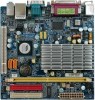
GA-7CN700ID
Motherboard Layout
.............................................................................
3
Block Diagram
................................................................................................................
4
Chapter 1 Hardware Installation
.....................................................................................
5
1-1
Considerations Prior to Installation
....................................................................
5
1-2
Feature Summary
............................................................................................
6
1-3
Installation of Memory
......................................................................................
7
1-4
Installation of Expansion Cards
........................................................................
8
1-5
I/O Back Panel Introduction
.............................................................................
9
1-6
Connectors Introduction
..................................................................................
10
Chapter 2
BIOS Setup
.................................................................................................
19
The Main Menu (For example: BIOS Ver. : F2e)
......................................................
20
2-1
Standard CMOS Features
.............................................................................
22
2-2
Advanced BIOS Features
..............................................................................
24
2-3
Advanced Chipset Features
...........................................................................
27
2-4
Integrated Peripherals
.....................................................................................
30
2-5
Power Management Setup
.............................................................................
34
2-6
PnP/PCI Configurations
.................................................................................
37
2-7
PC Health Status
...........................................................................................
38
2-8
Frequency/Voltage Control
.............................................................................
39
2-9
Load Fail-Safe Defaults
...................................................................................
40
2-10
Load Optimized Defaults
.................................................................................
40
2-11
Set Supervisor/User Password
.....................................................................
41
2-12
Save & Exit Setup
.........................................................................................
42
2-13
Exit Without Saving
.......................................................................................
42
 1
1 2
2 3
3 4
4 5
5 6
6 7
7 8
8

