Gigabyte B560M AORUS PRO AX User Manual - Page 22
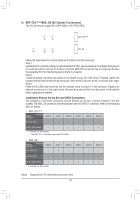
THB_C1/THB_C2 Thunderbolt, Add-in Card Connectors, SPI_TPM Trusted Platform Module Header
 |
View all Gigabyte B560M AORUS PRO AX manuals
Add to My Manuals
Save this manual to your list of manuals |
Page 22 highlights
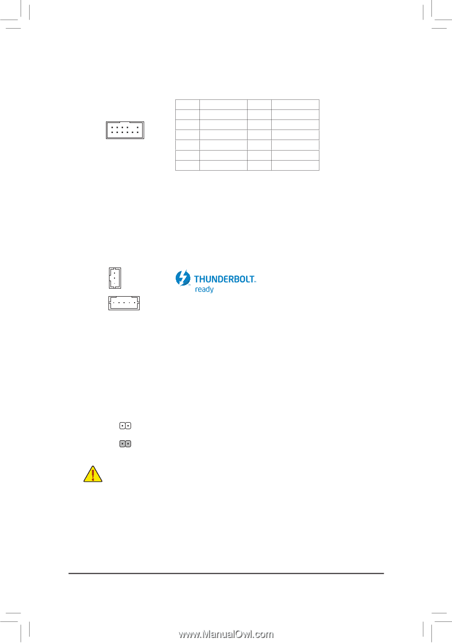
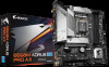
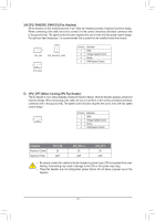
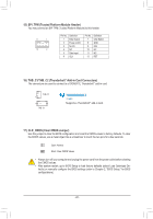
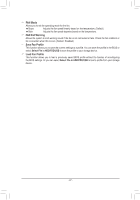
B_ B_ S _S S_ S_ _ _B _U _ F B F_USB3 F U 15) SPI_TPM (Trusted Platform Module Header) _ 0 You may connect an SPI TPM (Trusted Platform Module) to this header. Pin No. Definition Pin No. Definition _ 1S1 _ 1 1 Data Output 7 Chip Select B_ 2 Power (3.3V) 8 GND 3 No Pin _ 9F IRQ 12 2 4 NC 10 NC 5 Data Input 11 NC 6 CLK B_ 12 RST F_USB3 F_USB30 3 _0 F USB 0_ B _ S F_ B 16) THB_C1/THB_C2 (Thunderbolt™ Add-in Card Connectors) The connectors are used to connect to a GIGABYTE Thunderbolt™ add-in card. B_ USB 0_ B THB_C2 1 B_ 1 THB_C1 B_ B Supports a Thunderbolt™ add-in card. _ S F_ _3 U F_USB3 B 17) CLR_CMOS (Clear CMOS Jumper) Use this jumper to clear the BIOS configuration and reset the CMOS values to factory defaults. To clear the CMOS values, use a metal object like a screwdriver to touch the two pins for a few seconds. S F_ 3 F_USB30 3 Open: Normal F_USB30 3 B_ Short: Clear CMOS Values S _S B_ _ _ _B _ S_ •• Always turn off your computer and unplug the power cord from the power outlet before clearing the CMOS values. •• After system restart, go to BIOS Setup to load factory defaults (select Load Optimized Defaults) or manually configure the BIOS settings (refer to Chapter 2, "BIOS Setup," for BIOS configurations). _ SF _ __ 3 S3 B SS S U _S S_ _ B _U _ B F_USB3 F - 22 - _ _0 _3
-
 1
1 -
2
-
3
-
4
-
5
-
6
-
7
-
8
-
9
-
10
-
11
-
12
-
13
-
14
-
15
-
16
-
 17
17 -
 18
18 -
 19
19 -
 20
20 -
 21
21 -
 22
22 -
 23
23 -
 24
24 -
 25
25 -
 26
26 -
 27
27 -
28
-
29
-
30
-
31
-
32
-
33
-
34
-
35
-
36
-
37
-
38
-
39
-
40
-
41
-
42
-
43
-
44
-
45
-
46
-
47
-
48
-
49
-
50
-
51
-
52
 |
 |