Gigabyte GA-2AIEL5-RH Manual - Page 15
pin ATX power connectors
 |
View all Gigabyte GA-2AIEL5-RH manuals
Add to My Manuals
Save this manual to your list of manuals |
Page 15 highlights
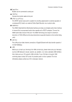
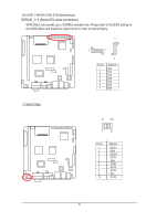
20-pin ATX power connectors Connector Introduction With the use of the power connector, the power supply can supply enough stable power to all the components on the motherboard. Before connecting the power connector, please make sure that all components and devices are properly installed. Align the power connector with its proper location on the motherboard and connect tightly. 10 20 1 11 Pin No. 1 2 3 4 5 6 7 8 9 10 + 11 12 3.3V 3.3V GND +5V GND +5V GND Power Good 5V SB(stand by +5V) 12V +12V(Only for 24-pin ATX) 3.3V(Only for 24-pin ATX) Pin No. 13 14 15 16 17 18 19 20 3.3V -12V GND PS_ON(soft On/Off) GND GND GND -5V 15
-
 1
1 -
2
-
3
-
4
-
5
-
6
-
7
-
8
-
9
-
 10
10 -
 11
11 -
 12
12 -
 13
13 -
 14
14 -
 15
15 -
 16
16 -
 17
17 -
 18
18 -
 19
19 -
 20
20 -
21
-
22
-
23
-
24
-
25
-
26
-
27
-
28
-
29
-
30
-
31
-
32
-
33
-
34
-
35
-
36
-
37
-
38
 |
 |

15
Connector Introduction
20-pin ATX power connectors
With the use of the power connector, the power supply can supply enough stable power to all
the components on the motherboard.
Before connecting the power connector, please make
sure that all components and devices are properly installed.
Align the power connector with
its proper location on the motherboard and connect tightly.
20
10
1
11
13
3.3V
14
-12V
15
GND
16
PS_ON(soft On/Off)
17
GND
18
GND
19
GND
20
-5V
Pin No.
Pin No.
1
3.3V
2
3.3V
3
GND
4
+5V
5
GND
6
+5V
7
GND
8
Power Good
9
5V SB(stand by +5V)
10 +
12V
11
+12V(Only for 24-pin
ATX)
12
3.3V(Only for 24-pin ATX)