Gigabyte GA-2AIEL5-RH Manual - Page 20
BATTERY, CAUTION, F_Panel, 2X5 Pins Front Panel connector
 |
View all Gigabyte GA-2AIEL5-RH manuals
Add to My Manuals
Save this manual to your list of manuals |
Page 20 highlights
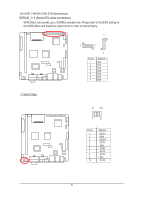
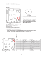
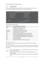
GA-2AIEL1-RH/GA-2AIEL5-RH Motherboard BATTERY F_USB F_1394 Serial ATA F1_1394 CAUTION Danger of explosion if battery is incorrectly replaced. SPDIF Replace only with the same or equivalent type recommended by the manufacturer. COMB If you want to erase CMOS... 1.Turn OFF the computer and unplug the power cord. 2.Remove the battery, wait for 30 second. 3.Re-install the battery. 4.Plug the power cord and turn ON the computer. Dispose of used batteries according to the manufacturer's instruAcUtXi_oINns. CD_IN F_Panel (2X5 Pins Front Panel connector) CPU_FAN SYS_FAN PWR_FAN Please connect the power LED, PC speaker, reset switch and power switch of your chassis front panel to the F_PANEL connector according to the pin assignment above. COMB 12 NB_FAN 9 10 WOL Pin No. Signal Name Description 1. HDD_LED+ Hard Disk LED Signalanode (+) Power 2. POWER LED+ Power LED Signal anode (+) 3. HD_LED- Hard Disk LED Signal cathode(-) 4. POWER LED- Power LED Signal cathode(-) 5. GND Ground 6. POWER SW+ Power Button Signal anode (+) 7. RES Reset Button 8. GND Ground 9. NC No connect 10. NC Pin removed F2_1394 20
-
 1
1 -
2
-
3
-
4
-
5
-
6
-
7
-
8
-
9
-
10
-
11
-
12
-
13
-
14
-
 15
15 -
 16
16 -
 17
17 -
 18
18 -
 19
19 -
 20
20 -
 21
21 -
 22
22 -
 23
23 -
 24
24 -
 25
25 -
26
-
27
-
28
-
29
-
30
-
31
-
32
-
33
-
34
-
35
-
36
-
37
-
38
 |
 |
